
Dust removal device for electrical engineering based on spraying mechanism and using method of dust removal device

A technology of electrical engineering and dust removal device, which is applied in the field of electrical engineering and can solve problems such as low dust removal efficiency, secondary pollution, and dust pollution of the environment

Active Publication Date: 2021-06-01
广东粤湛环保科技有限公司
View PDF15 Cites 3 Cited by
  • Summary
  • Abstract
  • Description
  • Claims
  • Application Information

AI Technical Summary

Problems solved by technology

[0003] There is often a lot of dust floating in the work room of electrical engineering operations, so it is necessary to use a dust removal device to remove dust, which is beneficial to the health of the staff. However, the current dust removal device has no follow-up treatment for the absorbed and stored dust, which may cause the dust to float again. The environment is polluted in the air, causing secondary pollution, resulting in low dust removal efficiency. In view of this, we propose a dust removal device for electrical engineering based on a spray mechanism and its use method

Method used


Image

  • Dust removal device for electrical engineering based on spraying mechanism and using method of dust removal device
  • Dust removal device for electrical engineering based on spraying mechanism and using method of dust removal device
  • Dust removal device for electrical engineering based on spraying mechanism and using method of dust removal device

Examples


Embodiment 1

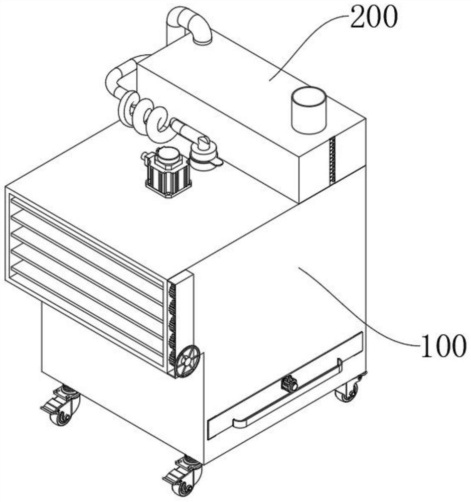
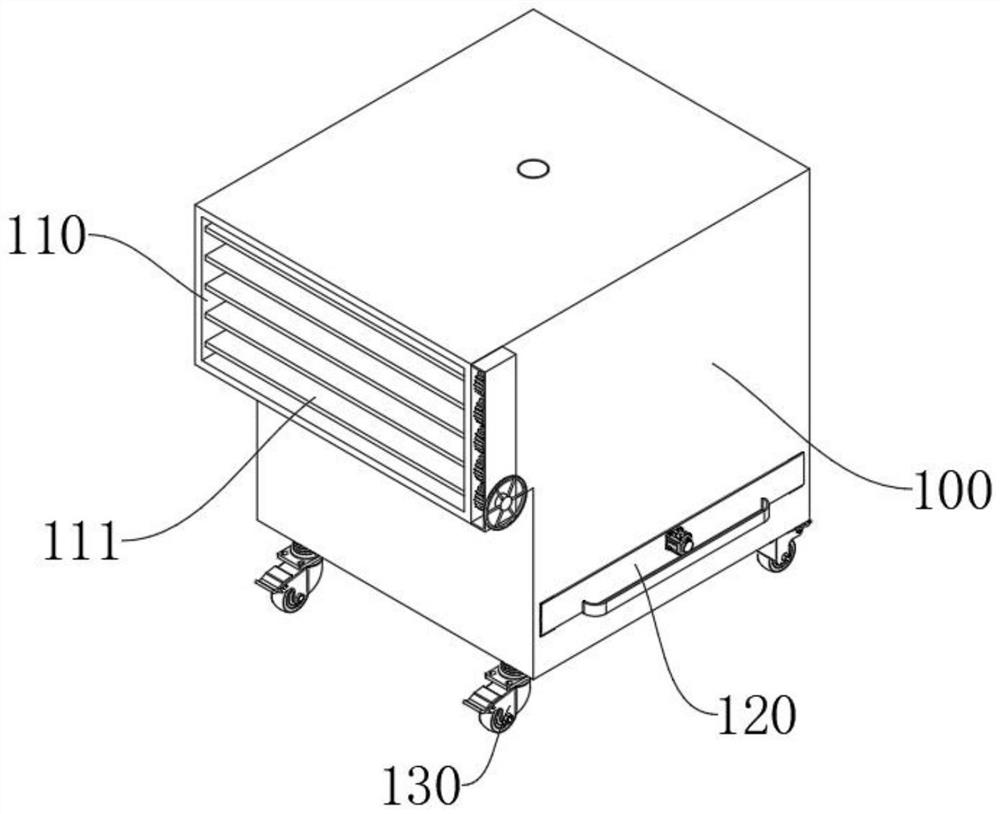
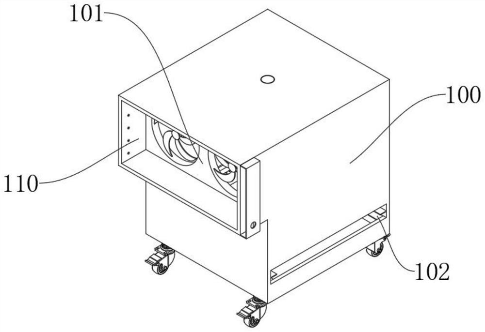
[0063] see Figure 1-Figure 15 As shown, the present embodiment provides a dust removal device for electrical engineering based on a spray mechanism, including a dust removal box 100 and a spray mechanism 200 at the top of the dust removal box 100. The outer wall of the dust removal box 100 near the top is connected with a dust inlet 110, and the spray mechanism 200 including at least:

[0064] Water tank 210, the water tank 210 is located at the top of the dust removal box 100, the water tank 210 is made of transparent plastic, the top of the water tank 210 is connected with a water adding pipe 211, by setting the water adding pipe 211, water can be added to the inside of the water tank 210 from the end of the water adding pipe 211, so that the inside of the water tank 210 The water in the water tank is kept sufficient, which is convenient for subsequent spraying of the dust inside the dust removal box 100, which is beneficial to the effect of dust reduction. The outer wall o...


PUM


Abstract

The invention relates to the technical field of electrical engineering, in particular to a dust removal device for electrical engineering based on a spraying mechanism and a using method of the dust removal device. The dust removal device comprises a dust removal box and a spraying mechanism at the top of the dust removal box. The outer wall, close to the top, of the dust removal box is communicated with a dust inlet. The spraying mechanism at least comprises a water tank, a water conveying pipe and a spraying device. The water tank is located at the top of the dust removal box. The other end of the water conveying pipe is communicated with a connecting cylinder, and an external thread is arranged on the outer wall, close to the bottom, of the connecting cylinder. The spraying device comprises a communicating rod, the communicating rod is rotationally arranged in the dust removal box, the outer wall, close to the top, of the communicating rod is communicated with two symmetrical spraying rods, the spraying rods are in an inverted L shape, the inner walls of the spraying rods are communicated with a plurality of water spraying heads at equal intervals, and the end of the communicating rod rotationally penetrates out of the dust removal box and is rotationally communicated with a connecting sleeve. By means of the dust removal device, sucked dust can be effectively subjected to dust suppression, the situation that the dust floats out again to pollute the environment is avoided, and atomized water can be directly sprayed for dust suppression in a workshop of electrical engineering.

Description

technical field [0001] The invention relates to the technical field of electrical engineering, in particular to an electrical engineering dust removal device based on a spray mechanism and a method for using the same. Background technique [0002] Electrical engineering is one of the core disciplines in the field of modern science and technology, and it is an indispensable key discipline in the field of high-tech electrical engineering. For example, it is the great progress of electronic technology that promotes the arrival of the information age based on computer networks. , and will change the way of human life and work; [0003] There is often a lot of dust floating in the work room of electrical engineering operations, so it is necessary to use a dust removal device to remove dust, which is beneficial to the health of the staff. However, the current dust removal device has no follow-up treatment for the absorbed and stored dust, which may cause the dust to float again. ...

Claims


Application Information

Patent Timeline
Patent Type & Authority Applications(China)
IPC IPC(8): B01D47/06B01D35/027B01D29/03B01D29/64B01D29/96
CPCB01D47/06B01D35/027B01D29/03B01D29/6423B01D29/96B01D2247/14B01D2247/04
Inventor 张鹏
Owner 广东粤湛环保科技有限公司
Learn More