
Lossless clamping network of primary side feedback flyback converter and design method

A flyback converter, primary-side feedback technology, applied in the field of electronics, can solve the problems of complex circuit structure, increasing the difficulty of driving circuit, converter cost, low topology efficiency, etc.

Active Publication Date: 2021-05-28
XI'AN PETROLEUM UNIVERSITY
View PDF7 Cites 1 Cited by
  • Summary
  • Abstract
  • Description
  • Claims
  • Application Information

AI Technical Summary

Problems solved by technology

[0005] (1) The traditional active clamping network is effective in suppressing peak voltage, but each main circuit requires a set of independent active clamping circuits, especially when the main circuit is multi-channel interleaved and paralleled, which increases the difficulty and transformation of the driving circuit device cost
[0006] (2) The traditional RCD clamp consists of diodes, clamp resistors and clamp capacitors. The topology of the RCD clamp network is simplified and can suppress peak voltages. However, the leakage inductance energy absorbed by the clamp network is dissipated on the resistance heating, resulting in topological low efficiency
The clamp capacitor used in this LCD clamp has a large capacity, which effectively ensures the stability of the clamp voltage, but also delays the response speed, so it is not suitable for the primary side feedback flyback converter that requires high response speed.
[0009] (5) The active clamping network is commonly used, and the diode in the clamping network is replaced by a field effect transistor. Although the efficiency of the active clamping network is slightly improved compared with the efficiency of the traditional clamping network, the active clamping network requires a special The drive circuit has a complex circuit structure and has the disadvantage of slow response speed

Method used


Image

  • Lossless clamping network of primary side feedback flyback converter and design method
  • Lossless clamping network of primary side feedback flyback converter and design method
  • Lossless clamping network of primary side feedback flyback converter and design method

Examples


Embodiment

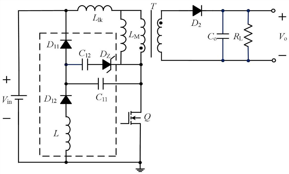
[0104] This embodiment relates to a novel lossless clamping network of a primary-side feedback flyback converter, including: a capacitor C 11 and C 12 , inductor L, diode D 11 and D 12 , the Zener diode Dz; the clamping network consists of three branches, namely the capacitor C 11 and C 12 Parallel branch, diode D 11 branch, diode D 12 A branch connected in series with the inductor L;

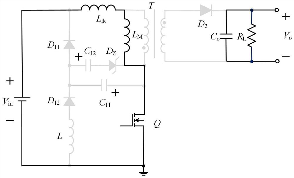
[0105] The capacitor C 11 and C 12 Parallel branch, large capacitor C 12 It can suppress the voltage overshoot during the turn-off process of the switch tube, and realize the clamping function, so that the switch tube does not have to bear high voltage stress to cause damage, and the small capacitance C 11 It can ensure that the response speed of the clamping network is fast;

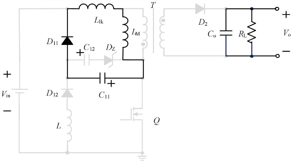
[0106] The diode D 11 The branch is turned on when the switch tube is turned off, and the capacitor C 11 and C 12 The parallel branch constitutes the leakage inductance energy transfer circuit, which provide...


PUM


Abstract

The invention provides a novel lossless clamping network of a primary side feedback flyback converter and a design method. The novel lossless clamping network comprises capacitors C11 and C12, an inductor L, diodes D11 and D12, and a voltage stabilizing diode Dz, and is composed of three branches, namely a branch formed by connecting the capacitors C11 and C12 in parallel, a branch of the diode D11 and a branch formed by connecting the diode D12 and the inductor L in series. According to the invention, double capacitors with different capacities are connected in parallel, the large capacitor C12 effectively suppresses voltage overshoot and achieves the clamping function, and the small capacitor C11 improves the response speed; according to different properties of branches, the clamping network is composed of three branches: a capacitor C11 and a capacitor C12 are connected in parallel, so that the response speed is improved, and the voltage peak in the switching-off process of a switching tube is suppressed; the branch of the diode D11 is conducted in the switching-off process of the switching tube, so that a channel is provided for transferring leakage inductance energy to the clamping network; and the diode D12 and the inductor L are connected in series to form a branch, and the capacitor is fed back to store energy in an LC resonance mode in the switching-on process of the switching tube, so that partial drain current of the switching tube is formed.

Description

technical field [0001] The invention relates to an electronic field; in particular, it relates to a novel lossless clamping network and a design method of a primary-side feedback type flyback converter. Background technique [0002] Due to the advantages of simple structure, small size and low cost, the flyback converter has high application value in small and medium power applications, especially the primary side feedback flyback converter, because of its excellent isolation performance, it is more applicable to widely. However, due to the inevitable leakage inductance of the transformer that plays the role of isolation and energy storage in the converter, a huge voltage spike will be generated at the moment the switch tube is turned off, causing the switch tube to withstand high voltage stress, and may even cause the switch tube to be damaged. , affecting the stable operation of the converter; at the same time, the leakage inductance loss reduces the efficiency of the fly...

Claims


Application Information

Patent Timeline
IPC IPC(8): H02M3/335
CPCH02M3/33523Y02B70/10
Inventor 宋久旭杨可李克艰李恩浩
Owner XI'AN PETROLEUM UNIVERSITY
Learn More