
Waterproof case of battery

A chassis and battery technology, applied to battery pack parts, circuits, electrical components, etc., can solve problems such as high labor costs, limited size of waterproof tank, complex structure of adapter plate, etc., to reduce production costs, simplify assembly, and save energy Effect of material cost and labor cost

Pending Publication Date: 2021-05-28
SHENZHEN COMPTON TECH
View PDF0 Cites 2 Cited by
  • Summary
  • Abstract
  • Description
  • Claims
  • Application Information

AI Technical Summary

Problems solved by technology

[0002] The waterproof structure of the battery case in the prior art is extremely complex. It consists of the main body of the case, an adapter plate and a top cover assembly. The structure of the adapter plate is complex, with many structural bends and gaps. Due to the limited size of the waterproof groove, it cannot be directly riveted Nut posts, so copper studs need to be transferred, the cost will naturally increase, the assembly is difficult, and the labor cost is high
Waterproof treatment requires not only glue filling, but also glue strips. It is difficult to handle the interface of the strips, and water often occurs; and because the strips are compressed, they must be fixed with screws from the top of the top cover. Complete the compression of the rubber strip to make it waterproof. Many screws need to be assembled, the processing is cumbersome, the assembly is difficult, and the workload and labor costs are virtually increased.
[0003] Another battery case waterproof structure in the prior art, the top cover of the case is made of plastic parts, while the main body of the case is made of sheet metal, the overall structure is simple, but because the plastic parts need to be molded, the cost of mold making is high and the cost is high

Method used


Image

  • Waterproof case of battery
  • Waterproof case of battery
  • Waterproof case of battery

Examples


Embodiment Construction

[0027] In order to make those skilled in the art more clearly understand the purpose, technical solutions and advantages of the present invention, the present invention will be further described below in conjunction with the accompanying drawings and embodiments. Embodiments of the present invention are described in detail below, examples of which are shown in the drawings, wherein the same or similar reference numerals designate the same or similar elements or elements having the same or similar functions throughout. The embodiments described below by referring to the figures are exemplary and are only used for explaining the patent, and should not be construed as limiting the patent.

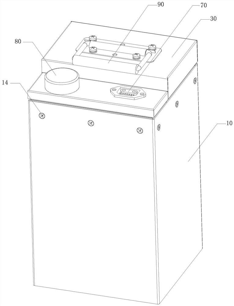
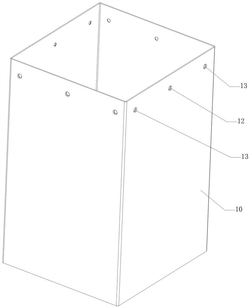
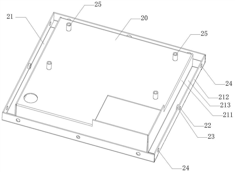
[0028] Such as Figure 1-8 As shown, in one embodiment of the present invention, the battery waterproof case includes a case main body 10 , an adapter plate 20 and a case top cover 30 . The edges of the sides of the adapter plate 20 are bent to form a waterproof groove 21 with a U-shaped cros...


PUM


Abstract

The invention discloses a waterproof case for a battery. The waterproof case comprises a case main body, an adapter plate and a case top cover, the edge of the side edge of the adapter plate is bent to form a waterproof groove with a U-shaped cross section; the adapter plate is mounted in the inner side of the case main body through screws, the outer wall of an outer side plate of the waterproof groove is tightly attached to the inner wall of the case main body, and the adapter plate is connected with the case main body to form a battery bin for placing a battery cell module in the case main body; the side edge of the case top cover is correspondingly inserted into the waterproof groove of the adapter plate, and the case top cover, the adapter plate and the case main body are locked through screws; and the waterproof groove is filled with a sealing glue solution, and the liquid level of the sealing glue solution is higher than the height of an outer side plate of the waterproof groove and lower than the height of an inner side plate of the waterproof groove. The number of screws which do not need to be assembled is small, assembling is easy and convenient, the material cost and the labor cost are saved, and the overall production cost is greatly reduced.

Description

technical field [0001] The invention relates to the technical field of batteries, in particular to a battery waterproof case. Background technique [0002] The waterproof structure of the battery case in the prior art is extremely complex. It consists of the main body of the case, an adapter plate and a top cover assembly. The structure of the adapter plate is complex, with many structural bends and gaps. Due to the limited size of the waterproof groove, it cannot be directly riveted Nut posts, so copper studs need to be transferred, the cost will naturally increase, the assembly is difficult, and the labor cost is high. Waterproof treatment requires not only glue filling, but also glue strips. It is difficult to handle the interface of the strips, and water often occurs; and because the strips are compressed, they must be fixed with screws from the top of the top cover. To complete the compression of the rubber strip to make it waterproof, many screws need to be assembled,...

Claims


Application Information

Patent Timeline
Patent Type & Authority Applications(China)
IPC IPC(8): H01M50/244
CPCY02E60/10
Inventor 吴波田波陈家峰周红平刘晓军陈加杰
Owner SHENZHEN COMPTON TECH
Learn More