Current limiting circuit of high-voltage large-current linear voltage regulator and implementation method

A technology of linear voltage regulator and current-limiting circuit, which is applied in the direction of instruments, adjusting electric variables, control/regulation systems, etc. It can solve problems such as inaccurate current-limiting value, increased power consumption, inaccurate current-limiting value of current-limiting structure, etc.

Active Publication Date: 2021-05-28
HITENX (WUXI) TECH CO LTD +1
View PDF6 Cites 1 Cited by
  • Summary
  • Abstract
  • Description
  • Claims
  • Application Information

AI Technical Summary

Problems solved by technology

However, most of the existing low-dropout linear regulator current limiting structures are realized by detecting the current of the power tube. The specific implementation method is to detect the current of the detection tube that is matched with the power tube and has a certain proportion When the set value is exceeded, the current limit occurs and a current limit action signal is issued. When the detection tube is small and the ratio of the power tube to the detection tube is too large, it is easy to cause the current limit value to be inaccurate, resulting in an error in the low dropout linear regulator. Action; when the detection tube is large and the ratio of the power tube to the detection tube is small, the current limit value is more accurate, but it will cause an increase in power consumption, especially in low-power low-dropout linear regulators. At the same time, the power tube and the The matching degree of the detection tube, the channel length modulation effect and the non-ideality of the analog circuit itself will all cause inaccurate current limiting value of the current limiting structure

Method used


Image

  • Current limiting circuit of high-voltage large-current linear voltage regulator and implementation method
  • Current limiting circuit of high-voltage large-current linear voltage regulator and implementation method
  • Current limiting circuit of high-voltage large-current linear voltage regulator and implementation method

Examples


Embodiment 1

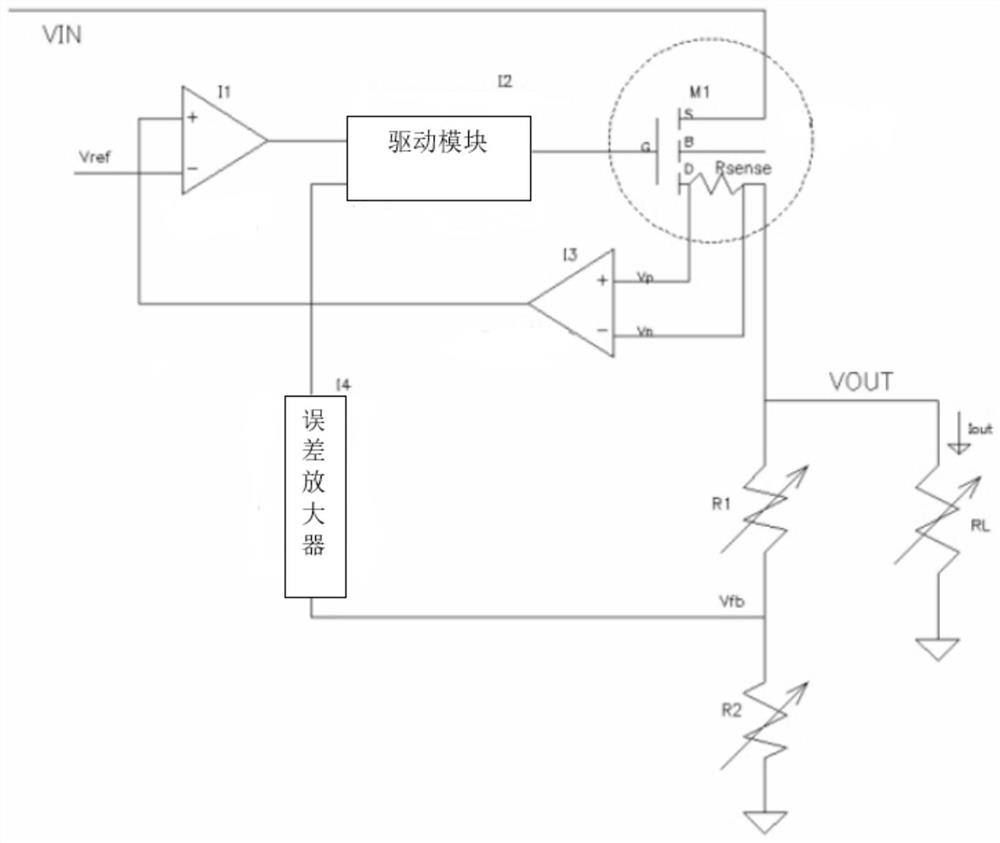
[0057] A current-limiting circuit of a high-voltage and large-current linear regulator includes a high-voltage output power tube M1, a sampling resistor Rsense, a current-limiting comparator I1, a drive module I2, a current sense amplifier I3, an error amplifier I4, a variable resistor R1, and a variable Divider resistance R2 and load equivalent resistance RL;

[0058] The source of the high-voltage output power transistor M1 is connected to the input voltage VIN, the gate of the high-voltage output power transistor M1 is connected to the first interface of the drive module I2, and the drain of the high-voltage output power transistor M1 and the first interface of the current sense amplifier I3 are connected to the sampling The first terminal of the resistor Rsense, the second interface of the current sense amplifier I3, the second terminal of the variable resistor R1 and the second terminal of the load equivalent resistor RL are all connected to the second terminal of the samp...

Embodiment 2

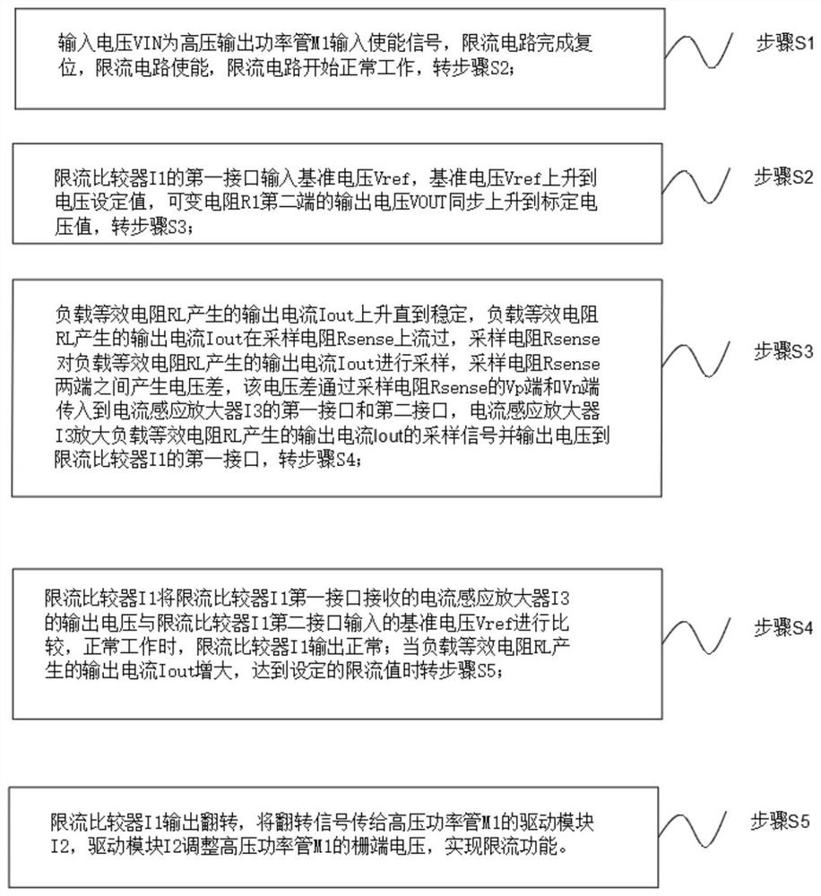
[0064] A method for realizing a current-limiting circuit of a high-voltage and high-current linear regulator comprises the following steps:

[0065] The input voltage VIN is the input enabling signal of the high-voltage output power transistor M1, the current limiting circuit is reset, the current limiting circuit is enabled, and the current limiting circuit starts to work normally;

[0066] The first interface of the current-limiting comparator I1 inputs the reference voltage Vref, the reference voltage Vref rises to the voltage setting value, and the output voltage VOUT of the second terminal of the variable resistor R1 rises to the calibrated voltage value synchronously;

[0067] The output current Iout generated by the load equivalent resistance RL rises until it is stable, the output current Iout generated by the load equivalent resistance RL flows through the sampling resistor Rsense, and the sampling resistor Rsense samples the output current Iout generated by the load e...

Embodiment 3

[0070] A method for realizing a current-limiting circuit of a high-voltage and high-current linear regulator comprises the following steps:

[0071] The input voltage VIN is the input enabling signal of the high-voltage output power transistor M1, the current limiting circuit is reset, the current limiting circuit is enabled, and the current limiting circuit starts to work normally;

[0072] The first interface of the current-limiting comparator I1 inputs the reference voltage Vref, the reference voltage Vref rises to the voltage setting value, and the output voltage VOUT of the second terminal of the variable resistor R1 rises to the calibrated voltage value synchronously;

[0073] The output current Iout generated by the load equivalent resistance RL rises until it stabilizes, and the output current Iout generated by the load equivalent resistance RL flows through the sampling resistor Rsense, and the sampling resistor Rsense samples the output current Iout generated by the l...


PUM


Abstract

The invention discloses a current limiting circuit of a high-voltage large-current linear voltage regulator and an implementation method, the current limiting circuit is connected with a variable resistor R1 and a variable divider resistor R2 through a drain electrode of a high-voltage output power tube M1, one end of the variable resistor R1 is used as an output voltage VOUT port, a load equivalent resistor RL generates an output current Iout, the output current Iout flows through a sampling resistor Rsense, a voltage difference is generated between the two ends of the sampling resistor Rsense, the voltage difference is transmitted to a current induction amplifier I3, the current induction amplifier I3 amplifies a sampling signal and outputs voltage to a current limiting comparator I1, the current limiting comparator I1 compares the output voltage of the current induction amplifier I3 with reference voltage Vref input by the current limiting comparator I1, and therefore current limiting is achieved. The current limiting circuit is scientific and reasonable, is safe and convenient to use, can very accurately correspond to the actual loading capacity through aluminum wiring resistance sampling on the active region of the output end of the high-voltage power tube M1, and timely realizes current limiting.

Description

technical field [0001] The invention relates to the technical field of power supply management, in particular to a current-limiting circuit of a high-voltage and high-current linear regulator and a realization method thereof. Background technique [0002] In recent years, with the continuous development of the integrated circuit industry, various power management chips have also made great progress. Power management chips currently used in portable electronic products mainly include discrete devices such as switching regulators, charge pump regulators, low-dropout linear regulators, and PMU power management units. Low-dropout linear regulators have been well developed for their advantages of simple structure, good stability, small ripple, low cost, low noise, small size, low quiescent current, and easy integration into other chips. [0003] Low-dropout linear regulators generally have a current-limiting protection circuit part to prevent the chip from overheating. However,...

Claims


Application Information

Patent Timeline
Patent Type & Authority Applications(China)
IPC IPC(8): G05F1/56
CPCG05F1/561
Inventor 许卫明
Owner HITENX (WUXI) TECH CO LTD
Why Eureka
Try Eureka