Automatic straw sticking machine

A tube machine and automatic technology, applied in packaging and other directions, can solve the problems of lower production efficiency, slow production line speed, complicated production process, etc., and achieve the effect of reducing the use of labor, improving production efficiency, and improving accuracy

Inactive Publication Date: 2021-05-28
SUZHOU CITY TONGKE MACHINERY
View PDF7 Cites 0 Cited by
  • Summary
  • Abstract
  • Description
  • Claims
  • Application Information

AI Technical Summary

Problems solved by technology

[0002] The existing tube sticking production line for packaging has slow speed, poor stability, many operators, and the tube sticking position is manually controlled, so the positioning is inaccurate. At the same time, the production process is complicated, the production cost is high, and the production efficiency is also reduced.

Method used


Image

  • Automatic straw sticking machine
  • Automatic straw sticking machine
  • Automatic straw sticking machine

Examples


Embodiment Construction

[0021] In order to make the technical solutions of the present invention clearer and clearer to those skilled in the art, the present invention will be further described in detail below in conjunction with the examples and accompanying drawings, but the embodiments of the present invention are not limited thereto.

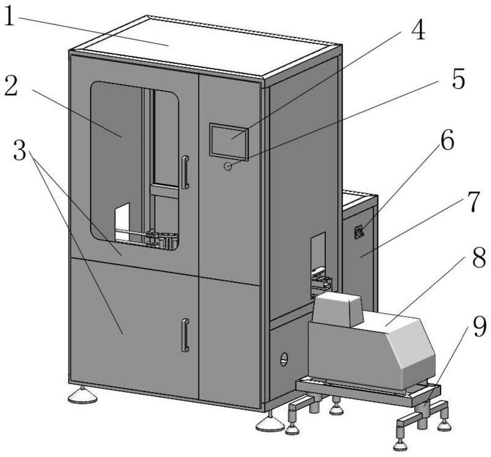
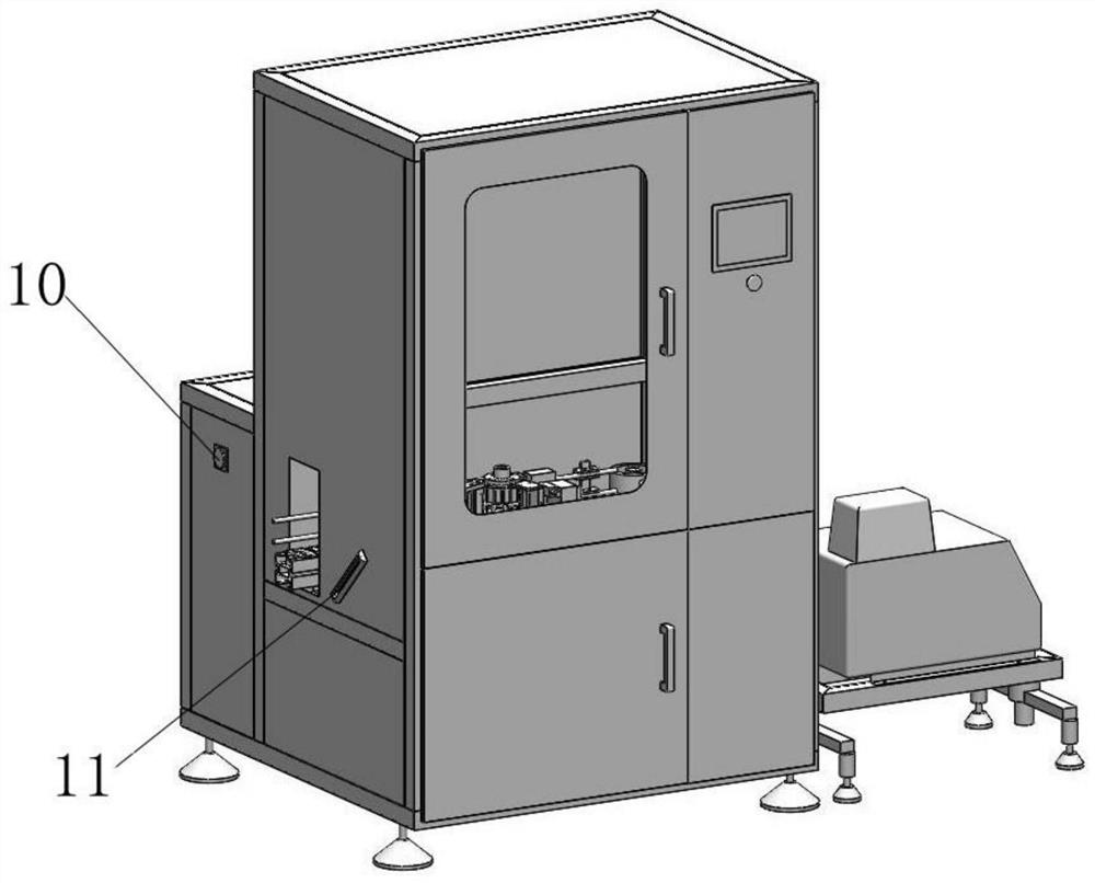
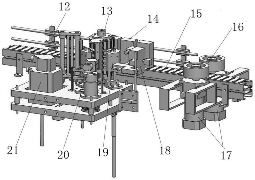
[0022] Such as Figure 1-Figure 4 As shown, the automatic tube sticking machine provided in this embodiment includes a body 1 and a drum assembly 13 installed inside the body 1. One side of the drum assembly 13 is provided with an in-machine conveyor chain 15, and the in-machine conveyor chain 15 There are multiple cartoning motors 17 slidingly connected to the lower part through two sets of support frames. The output end of the cartoning motor 17 is connected to the wheel box 16. The drum assembly 13 includes a tube sticking base 25 and a servo motor installed inside the tube sticking base 25 One side of the motor 21 and the drum assembly 13 is provided with a glu...


PUM


Abstract

The invention discloses an automatic straw sticking machine and belongs to the technical field of straw sticking production equipment. The automatic straw sticking machine comprises a machine body and a rotary drum assembly installed in the machine body, a built-in conveying chain is arranged on one side of the rotary drum assembly, a plurality of box separating motors are slidably connected to the lower portion of the built-in conveying chain through two sets of supporting frames, and the output ends of the box separating motors are connected with wheel separating boxes; and the rotary drum assembly comprises a straw sticking base and a servo motor installed in the straw sticking base, a glue spraying gun body is arranged on one side of the rotary drum assembly, and the output end of the servo motor is connected with a shifting fork mechanism through a rotary shaft. By arranging the rotary drum assembly and the shifting fork mechanism, straw sticking can be conducted on a brick-shaped box product, and the shifting fork mechanism extrudes a straw so that the straw can be more firmly pasted on the brick-shaped box product; and a photoelectric sensor is arranged, so that brick-shaped box products can be accurately positioned and separated, the box separation positioning accuracy is improved, manual box positioning and separation are not needed, and the production efficiency is improved.

Description

technical field [0001] The invention relates to a pipe lamination machine, in particular to an automatic pipe lamination machine, which belongs to the technical field of pipe lamination machine production equipment. Background technique [0002] The existing packaging tube sticking production line has slow speed, poor stability, many operators, and the tube sticking position is manually controlled, so the positioning is inaccurate. At the same time, the production process is complicated, the production cost is high, and the production efficiency is also reduced. Contents of the invention [0003] The main purpose of the present invention is to provide an automatic pipe sticking machine in order to solve the deficiencies of the prior art. [0004] The purpose of the present invention can be achieved by adopting the following technical solutions: [0005] An automatic pipe sticking machine, including a body and a drum assembly installed inside the body, one side of the drum...

Claims


Application Information

Patent Timeline
Patent Type & Authority Applications(China)
IPC IPC(8): B65B61/20
CPCB65B61/20
Inventor 王兵葛义
Owner SUZHOU CITY TONGKE MACHINERY
Why Eureka
Try Eureka