
Valve hot punching equipment

A red punching and equipment technology, which is applied in safety equipment, metal processing equipment, stripping devices, etc., can solve the problems of poor cooling effect of the dynamic and fixed molds of the valve red punching equipment, difficulty in demoulding the valve blank, and high labor intensity. , to achieve the effect of improving the cooling effect, eliminating potential safety hazards, and reducing labor intensity

Pending Publication Date: 2021-05-28
台州天巧自动化科技有限公司
View PDF0 Cites 0 Cited by
  • Summary
  • Abstract
  • Description
  • Claims
  • Application Information

AI Technical Summary

Problems solved by technology

[0002] The valve red punching equipment is an automatic equipment that can cut the copper rod according to a certain length, heat it red, and then extrude it to make the valve blank; the existing valve red punching equipment can make the copper rod into the valve blank , the valve blank cannot be discharged automatically, and can only be taken out manually, so the labor intensity is high, the work efficiency is low, and the operator directly contacts with the high-temperature valve blank, which has potential safety hazards; The cooling effect of the mold is also poor, which in turn makes it difficult to demould the valve blank. Once jamming occurs during demoulding, the machine must be stopped and the valve blank must be manually removed, resulting in interruption of production, which urgently needs to be resolved

Method used


Image

  • Valve hot punching equipment
  • Valve hot punching equipment
  • Valve hot punching equipment

Examples


Embodiment Construction

[0022] Unless otherwise defined, the technical terms or scientific terms used in the present invention shall have the usual meanings understood by those skilled in the art to which the present invention belongs. "First", "second" and similar words used in the present invention do not indicate any order, quantity or importance, but are only used to distinguish different components. "Comprising" or "comprising" and similar words mean that the elements or items appearing before the word include the elements or items listed after the word and their equivalents, without excluding other elements or items. Words such as "connected" or "connected" are not limited to physical or mechanical connections, but may include electrical connections, whether direct or indirect. "Up", "Down", "Left", "Right" and so on are only used to indicate the relative positional relationship. When the absolute position of the described object changes, the relative positional relationship may also change acc...


PUM


Abstract

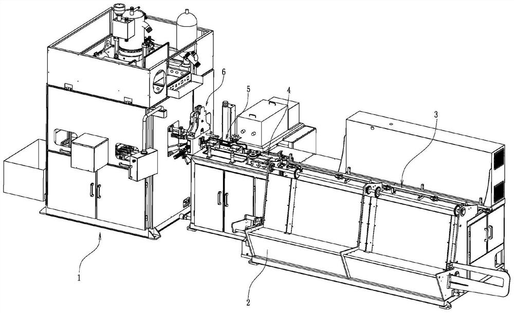
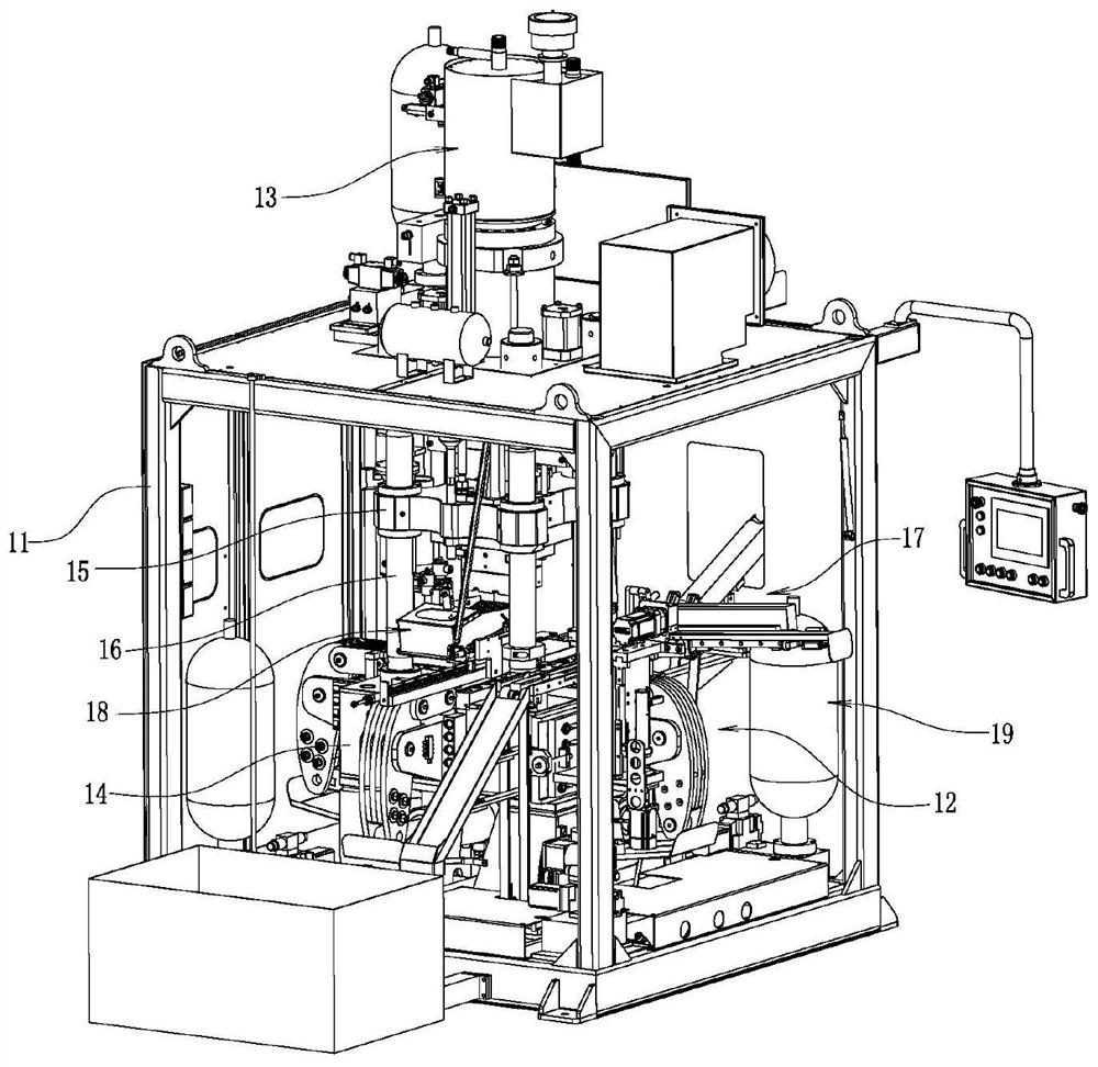
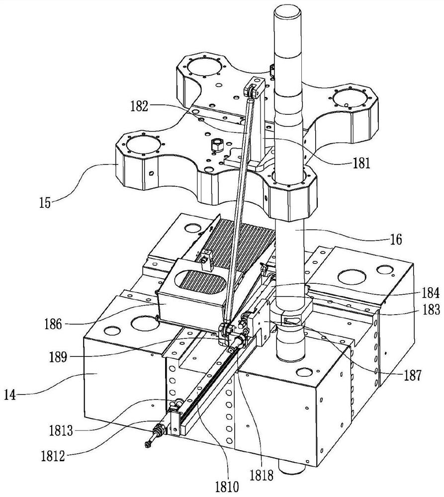
The invention relates to valve hot punching equipment which comprises a main machine, a table cabinet arranged on the right side of the main machine, and a feeding mechanism, a conveying mechanism, a heating mechanism and a cutting mechanism which are sequentially arranged on the top of the table cabinet from right to left. The main machine comprises a machine cabinet, an extrusion mechanism arranged at the bottom of the machine cabinet, a fixed mold arranged at the top of the extrusion mechanism, a material inlet mechanism arranged on one side of the fixed mold, four guide columns vertically fixed between the top of the machine cabinet and the fixed mold and symmetrically distributed in pairs, a movable mold movably arranged among the four guide columns, and a pressurizing mechanism arranged above the top of the machine cabinet and capable of driving the movable mold to move up and down along the four guide columns. The main machine further comprises a discharging mechanism and a cooling system. The valve hot punching equipment has an automatic discharging function, so that the labor intensity is greatly reduced, and the working efficiency is improved; In addition, by means of the cooling system, the cooling effect on the movable mold and the fixed mold is greatly improved, the demolding difficulty of a valve blank is lowered, and continuous production is guaranteed.

Description

technical field [0001] The invention relates to a valve red flushing device. Background technique [0002] The valve red punching equipment is an automatic equipment that can cut the copper rod according to a certain length, heat it red, and then extrude it to make the valve blank; the existing valve red punching equipment can make the copper rod into the valve blank , the valve blank cannot be discharged automatically, and can only be taken out manually, so the labor intensity is high, the work efficiency is low, and the operator directly contacts with the high-temperature valve blank, which has potential safety hazards; The cooling effect of the mold is also poor, which makes it difficult to demould the valve blank. Once jamming occurs during demoulding, the machine must be shut down and the valve blank must be manually removed, which leads to production interruption and urgently needs to be resolved. Contents of the invention [0003] Aiming at the current situation of...

Claims


Application Information

Patent Timeline
Patent Type & Authority Applications(China)
IPC IPC(8): B21D22/02B21D37/10B21D37/16B21D37/18B21D45/10B21D55/00
CPCB21D22/02B21D37/10B21D37/16B21D37/18B21D45/10B21D55/00
Inventor 周勇剑芦金奇屈理栋
Owner 台州天巧自动化科技有限公司
Learn More