Chemical feeding equipment

A kind of equipment and chemical technology, applied in the field of chemical powder feeding, which can solve the problems of crushing materials that cannot be agglomerated

Inactive Publication Date: 2021-05-28
陈培安
View PDF0 Cites 0 Cited by
  • Summary
  • Abstract
  • Description
  • Claims
  • Application Information

AI Technical Summary

Problems solved by technology

[0004] Aiming at the deficiencies in the existing technology, the purpose of the present invention is to provide a chemical feeding equipment to solve the problem in the prior art that when using a dust-free powder feeder to feed chemical powder activated carbon, the powder is uniformly fed downwards and coordinated The vibration of the vibrating sieve makes the powder double up and rise up. At the same time, it cannot effectively crush the agglomerated materials contained in the powder. Defects in the holes of the screen

Method used


Image

  • Chemical feeding equipment
  • Chemical feeding equipment
  • Chemical feeding equipment

Examples


no. 1 example

[0030] Such as Figure 1-Figure 3 As shown, the present invention provides a kind of technical scheme of chemical industry feeding equipment:

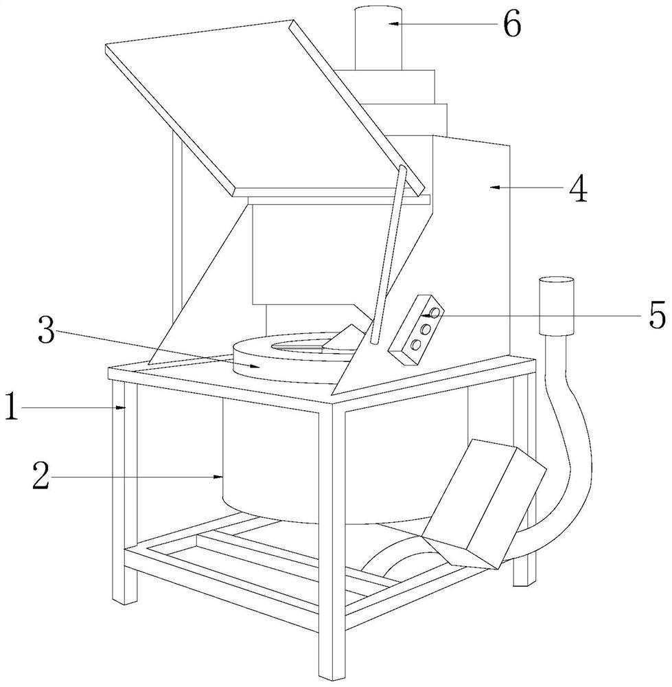
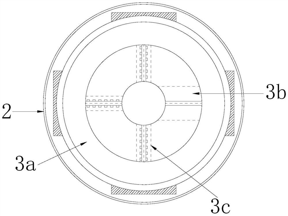
[0031] Such as Figure 1-Figure 2 As shown, a chemical feeding equipment, its structure includes a bracket 1, a vibrating screen drum 2, a circumflex crushing device 3, a feeding rack 4, a controller 5, and a drive motor 6, and the vibrating screen drum 2 is installed inside the bracket 1, The circumflex crushing device 3 is arranged on the upper surface of the vibrating screen cylinder 2, the feeding rack 4 is installed on the upper surface of the bracket 1, the controller 5 is arranged on the right side surface of the feeding rack 4, and the driving motor 6 is arranged on the feeding rack 4. On the upper surface of the frame 4, the circumflex crushing device 3 includes a sub-injection structure 3a, a crushing mechanism 3b, and a sieve structure 3c. The sub-injection structure 3a is installed on the upper surface of the vibrating scr...

no. 2 example

[0039] Such as Figure 4-Figure 7 As shown, the present invention provides a kind of technical scheme of chemical industry feeding equipment:

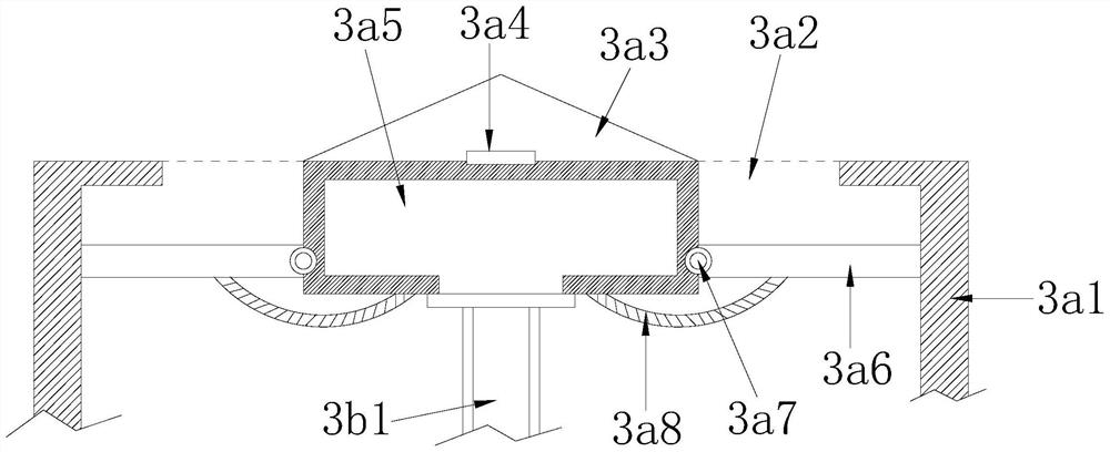
[0040] Such as Figure 4-Figure 5 As shown, a chemical feeding equipment, its structure includes the rolling mechanism 3b including a connecting pipe 3b1, a fixed frame plate 3b2, an overflow layer 3b3, and an extruding rod 3b4, and the connecting pipe 3b1 is arranged on the lower surface of the cavity frame 3a5 And through the connection, the fixed frame plate 3b2 is horizontally installed on the lower surface of the connecting pipe 3b1 and connected through the connection, the overflow layer 3b3 is provided on the lower surface of the fixed frame plate 3b2 and is an integrated structure, the matching There are more than eight rods 3b4 and they are installed on the lower surface of the fixed frame plate 3b2 in a uniform and equidistant shape, which is beneficial to realize the cooperation with the sieve structure 3c, squeeze the aggl...


PUM


Abstract

The invention discloses chemical feeding equipment. The chemical feeding equipment structurally comprises a support, a vibrating screen drum, a raising crushing device, a feeding frame, a controller and a driving motor. The chemical feeding device has the beneficial effects that under the cooperation of a conical block and a separate feeding ring, powder which is fed downwards is dispersed and flown so as to avoid the situation that the powder flying effect is increased due to the fact that a large amount of powder is fed downwards; through the cooperation of opening and closing plates, synchronous opening and closing are conducted on downward feeding of the powder so as to prevent the situation that after downward feeding is completed, the powder flows back and rises again in cooperation with the vibration effect of a vibrating screen, and the powder flying amount is doubled; under the action of rotary motion of a stroking and pressing piece, caked materials, discharged by the vibrating screen, in the powder are subjected to centralized stroking treatment; in cooperation with a grinding and extruding mechanism, the caked materials are extruded and mixed with one another so as to be broken; and meanwhile, in cooperation with airflow blown downwards, the crushed caked materials are blown downwards, so that the materials are prevented from being raised upwards and attached to the upper part in the grinding and extruding mechanism.

Description

technical field [0001] The invention relates to the field of chemical powder feeding, more precisely, it relates to chemical feeding equipment. Background technique [0002] With the wide variety and diversification of chemical products, chemical powders are widely used in various fields. Due to their production and processing, chemical powders themselves have certain harm to workers. Therefore, in its production and processing process, most of them adopt the mode of machine-based and artificial-assisted. [0003] When using a dust-free powder feeder to feed powdered activated carbon for chemical industry, the powder is uniformly fed downwards and combined with the vibration of the vibrating screen, so that the powder doubles and rises upwards. The bulk material is effectively crushed, and when the feeder vibrates the screen, there are local jams in the holes of the vibrating screen. Contents of the invention [0004] Aiming at the deficiencies in the existing technology...

Claims


Application Information

Patent Timeline
IPC IPC(8): B02C19/00B02C23/16B02C23/18
CPCB02C19/00B02C23/16B02C23/18B02C2023/165
Inventor 林小华
Owner 陈培安
Why Eureka
Try Eureka