Metal pipe equal-distance cutting equipment for high-end equipment

An isometric cutting, metal tube technology, applied in metal processing equipment, shearing equipment, shearing devices, etc., can solve the problems of inconsistency, long time consumption, low cutting efficiency, etc., to prevent displacement, precise cutting, and reduce noise. Effect

Active Publication Date: 2021-05-25
安徽鑫晟机械工业科技有限公司
View PDF13 Cites 0 Cited by
  • Summary
  • Abstract
  • Description
  • Claims
  • Application Information

AI Technical Summary

Problems solved by technology

[0004] In order to overcome the disadvantages of long cutting time, low cutting efficiency and inconsistent lengths of cut metal pipes, the technical problem of the present invention is to provide a cutting time-consuming, high cutting efficiency and uniform length of cut metal pipes. Metal pipe isometric cutting equipment with high end equipment

Method used


Image

  • Metal pipe equal-distance cutting equipment for high-end equipment
  • Metal pipe equal-distance cutting equipment for high-end equipment
  • Metal pipe equal-distance cutting equipment for high-end equipment

Examples


Embodiment 1

[0025] A metal pipe isometric cutting equipment for high-end equipment such as figure 1 As shown, base plate 1, support 2, cutting mechanism 3 and transport mechanism 4 are included. Support 2 is provided on the front and rear sides of base plate 1, cutting mechanism 3 is provided on the right side of support 2, and transport mechanism 4 is provided on the right side of base plate 1.

[0026] When people need to cut the material, the transport mechanism 4 is manually operated to transport the material. When the material is located below the cutting mechanism 3, the cutting mechanism 3 is started, and the cutting mechanism 3 starts cutting the material. After the cutting is completed, the transport mechanism is manually stopped. 4. Then close the cutting mechanism 3 and store the cut materials.

Embodiment 2

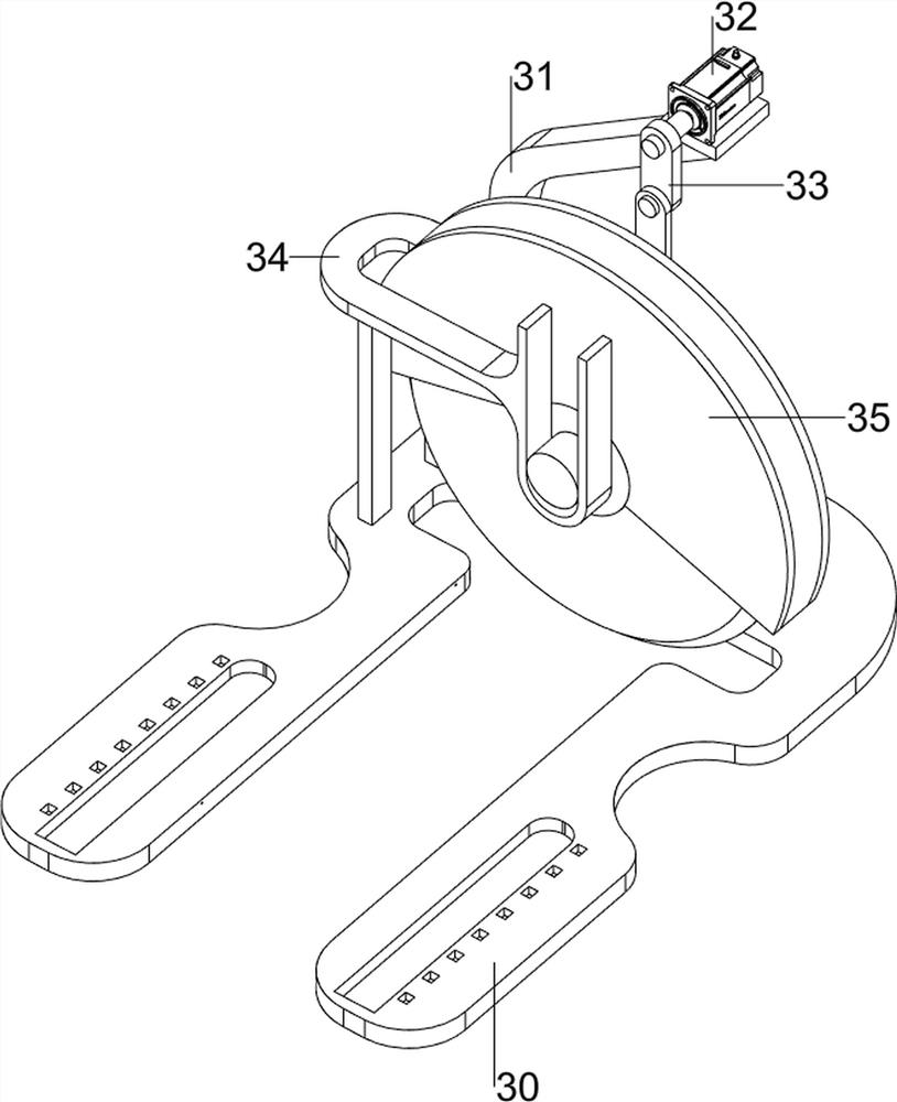
[0028] On the basis of Example 1, such as Figure 2 to Figure 8 As shown, the cutting mechanism 3 includes a mounting plate 30, a support base 31, a servo motor 32, a crank 33, a slide rail 34 and a cutter 35, the mounting plate 30 is connected between the tops of the brackets 2, and the right rear portion of the mounting plate 30 is provided with Slide rail 34, sliding type is connected with cutter 35 on the slide rail 34, and mounting plate 30 right rear parts are provided with support base 31, and support base 31 is provided with servo motor 32, and servo motor 32 output shafts and cutter 35 are all provided with. There are cranks 33, and the cranks 33 are rotatably connected.

[0029] When people need to cut the material, start the cutter 35, then start the servo motor 32, the servo motor 32 drives the cutter 35 to move up and down in the slide rail 34 through the crank 33, when the servo motor 32 drives the cutter 35 to move upwards, Manually transport the material to th...


PUM


Abstract

The invention relates to cutting equipment, in particular to metal pipe equal-distance cutting equipment for high-end equipment. The metal pipe equal-distance cutting equipment for the high-end equipment is short in cutting time, high in cutting efficiency and capable of cutting metal pipes with the same length. According to the technical implementation scheme, the metal pipe equal-distance cutting equipment for the high-end equipment comprises a bottom plate and supports, and the supports are arranged on the two sides of the bottom plate. The metal pipe equal-distance cutting equipment for the high-end equipment is characterized by further comprising a cutting mechanism and a conveying mechanism, the cutting mechanism is arranged on one sides of the supports, and the conveying mechanism is arranged on one side of the bottom plate. Through the effect of a noise reduction discharging mechanism, the noise generated by materials can be reduced when the materials are collected, and meanwhile, damage caused by material impact can be prevented.

Description

technical field [0001] The invention relates to a cutting device, in particular to a metal pipe equidistant cutting device for high-end equipment. Background technique [0002] Metal pipes are not only used to transport fluids and powdery solids, exchange heat, and manufacture mechanical parts and containers. The manufacture of highway bridges can not only save steel and simplify construction, but also greatly reduce the area of ​​the protective layer, saving investment and maintenance costs. [0003] When people need to cut metal pipes at equal intervals, they often use manual measurement, and then carry out the metal pipe, which takes a long time to cut, and the cutting efficiency is low. At the same time, the length of the cut metal pipes may be inconsistent. Therefore, a cutting method has been developed. Short time consumption, high cutting efficiency, and consistent length of cut metal tubes are metal tube equidistant cutting equipment for high-end equipment. Conten...

Claims


Application Information

Patent Timeline
IPC IPC(8): B23D19/00B23D33/02B23D33/00
CPCB23D19/00B23D33/02B23D33/006
Inventor 廖茜
Owner 安徽鑫晟机械工业科技有限公司
Why Eureka
Try Eureka