Microwave oven

A microwave oven and body technology, applied in the field of microwave ovens, can solve the problems of uneven heating, inability to achieve uniform heating, heating, and heating in one place.

Pending Publication Date: 2021-05-18
四川大学锦城学院
View PDF4 Cites 1 Cited by
  • Summary
  • Abstract
  • Description
  • Claims
  • Application Information

AI Technical Summary

Problems solved by technology

In the microwave oven, the common microwave heating method is that after putting the food into the microwave oven, through the rotation of the food placing table in the microwave oven, each area of ​​the food can be heated at the heating point, thereby ensuring the uniformity of heating; However, in the conventional heating method, uneven heating is often caused by the deviation of the placement position, especially for solid food, it often occurs that one part of the object to be heated has been heated, and one part has not yet been heated. , can not achieve the purpose of uniform heating

Method used


Image

  • Microwave oven
  • Microwave oven
  • Microwave oven

Examples


Embodiment 1

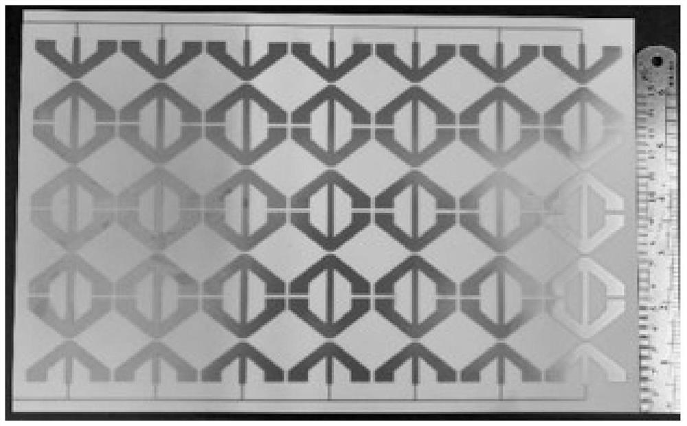
[0033] Such as figure 1 As shown, a microwave oven includes a microwave oven body 1, and an adjustable frequency selection surface 2 is arranged inside the microwave oven body 1, and the adjustable frequency selection surface 2 is arranged near the rear side wall 7 of the microwave oven body 1 (or according to According to actual needs, it is arranged on the left side wall 3, the right side wall 6, the upper side wall 8 or the lower side wall 9), one adjustable frequency selection surface 2 can be used, and multiple adjustable frequency selection surfaces 2 can also be used, adjustable The frequency selection surface 2 corresponds to the side wall one by one; in this embodiment, the distance between the adjustable frequency selection surface and the rear side wall 7 is 2-6 cm, and the adjustable frequency selection surface 2 separates the cavity in the microwave oven body 1 It is formed into a heating area 10 and an electric field boundary change area 11. An object holding pla...

Embodiment 2

[0039] The difference from Embodiment 1 is that in this embodiment, the object-to-be-heated holding platform 5 can rotate by itself in the microwave oven body 1 through a rotating mechanism. It can be understood that the rotation mode of the hot object holding platform 5 can be the rotation mode in the existing microwave oven, and the efficient heating of the microwave oven can be realized through the synergy between the rotation of the hot object holding platform 5 and the frequency selective surface 2, so that Items to be heated can be heated more evenly.

Embodiment 3

[0041] The difference from Embodiment 1 is that in this embodiment, in order to facilitate the cleaning of the interior of the microwave oven body 1, the adjustable frequency selection surface 2 can be set to be detachable, that is, in the microwave oven body 1 Slots are provided on the side walls (the slots are respectively located on the upper side wall 8 or the lower side wall 9 of the microwave oven body 1), and the adjustable frequency selection surface 2 can be directly inserted into the slots for positioning.

[0042] When the user opens the door of the microwave oven body 1, the frequency selection surface 2 can be seen intuitively, and the user pulls the adjustable frequency selection surface 2 by hand, and the adjustable frequency selection surface 2 can be pulled out from the slot , so as to clean the oil on the adjustable frequency selection surface 2, after the cleaning is completed, then insert the adjustable frequency selection surface 2 into the microwave oven b...


PUM


Abstract

The invention discloses a microwave oven. The microwave oven comprises a microwave oven body, a performance-adjustable frequency selection surface is arranged in the microwave oven body, the frequency selection surface is close to the side wall in the microwave oven body, and a cavity in the microwave oven body is divided into a heating area and an electric field boundary change area by the frequency selection surface. The control system on the adjustable frequency selective surface is connected with a controller of the microwave oven body; and a to-be-heated object containing table and a power input port are arranged in the heating area. The frequency selective surface is applied to the microwave oven, and the frequency selective surface is in a transmission or reflection state for microwaves by periodically changing the filtering characteristic of the frequency selective surface, so that the boundary of a microwave field is changed, the distribution state of an electric field in the microwave oven is changed, and the purpose of improving the heating uniformity is achieved.

Description

technical field [0001] The invention relates to the field of microwave heating, in particular to a microwave oven. Background technique [0002] Frequency Selective Surface (FSS) is a two-dimensional periodic array structure, which is a spatial filter in essence, and exhibits obvious band-pass or band-stop filtering characteristics when interacting with electromagnetic waves. FSS has a specific frequency selection effect and is widely used in microwave, infrared to visible light bands. The frequency selective surface is widely used, and can be used in the negative reflector of the reflector antenna to achieve frequency multiplexing and improve the utilization rate of the antenna; it can be used in wave polarizers, beam splitters and "cavity mirrors" of lasers to improve the efficiency of lasers. Pump power; can also be used in stealth technology, such as radome to reduce the radar cross section of the antenna system, etc. [0003] At present, no frequency selective surface...

Claims


Application Information

Patent Timeline
Patent Type & Authority Applications(China)
IPC IPC(8): H05B6/64H05B6/72F24C7/02
CPCH05B6/64H05B6/6402H05B6/72
Inventor 王成蓉
Owner 四川大学锦城学院
Why Eureka
Try Eureka