
Z-shaped compression-torsion metamaterial structure

A technology of metamaterials and beam structures, applied in the field of metamaterials, can solve problems such as insufficient stability of compression and torsion effects, high manufacturing difficulty, and complex structures

Pending Publication Date: 2021-05-18
FUDAN UNIV
View PDF0 Cites 0 Cited by
  • Summary
  • Abstract
  • Description
  • Claims
  • Application Information

AI Technical Summary

Problems solved by technology

[0003] Existing compression-torsion metamaterials often have disadvantages such as complex structure and high manufacturing difficulty, and the complex microstructure also makes the compression-torsion effect not stable enough.

Method used


Image

  • Z-shaped compression-torsion metamaterial structure
  • Z-shaped compression-torsion metamaterial structure
  • Z-shaped compression-torsion metamaterial structure

Examples


Embodiment 1

[0038] Use a 3D printer to print, the material used is TPU95A, and the water-soluble support material used is PVA.

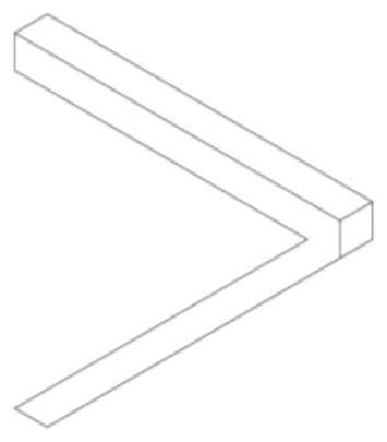
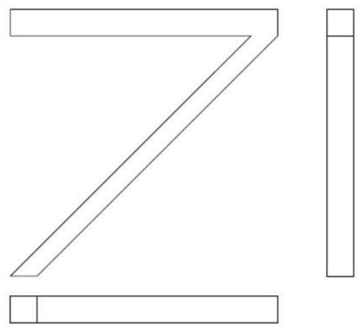
[0039] Embodiment 1, in-plane beam structure such as figure 2 As shown, its main structure is connected by 2 straight beams at 45°, the width of the short beams is 10mm, the width of the long beams (ie oblique beams) is about 7mm, and the thickness is 10mm.

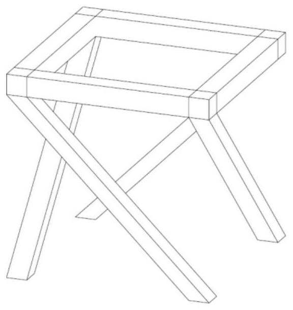
[0040] In embodiment 1, cell such as Figure 4 As shown, the cell is a square tube composed of four in-plane beams perpendicular to each other.

[0041] In Example 1, 1×1×8 is stacked as Figure 9 As shown, this stack is a structure of 8 cells arranged in 1 row, 1 column, and 8 layers.

[0042] After the printing is completed, soak the printed parts in water, and replace the clean water when the water becomes turbid until the PVA support completely disappears, and then dry it.

[0043] Such as Figure 9 , Figure 10 , Figure 11 , Figure 12 , Figure 13 and Figure 14 As shown, the 1×1×8 stacked...

Embodiment 2

[0045] The cell size in embodiment 2 is the same as that in embodiment 1, and the manufacturing method is also the same as in embodiment 1, so details are not repeated here.

[0046] In Example 2, 2×2×8 are stacked as Figure 16 As shown, this stack is a structure of 32 cells arranged in 2 rows, 2 columns, and 8 layers.

[0047] Such as Figure 16 , Figure 17 , Figure 18 , Figure 19 , Figure 20 and Figure 21 As shown, the 2×2×8 stacked compression-torsion superstructure undergoes obvious torsion after compression, as shown by Figure 18 , Figure 19 The measurable pressing distance is about 125mm, and the strain is 15.6%, which can be determined by Figure 22 The measurable torsion angle is about 18°, the radian is 0.314, the calculated angle-to-strain ratio is 1.15° / %, and the radian ratio is 0.02 / %.


PUM


Abstract

The invention belongs to the technical field of metamaterials, and particularly relates to a Z-shaped compression-torsion metamaterial structure. The metamaterial structure is formed by repeatedly stacking a plurality of cell elements, and each cell element is a square frame defined by four same in-plane beam structures which are perpendicular to one another; the in-plane beam structure is formed by connecting a positive beam and an inclined beam at an included angle of 45 degrees; the end parts of the positive beams in the four in-plane beam structures in the cell elements are connected to form a square, and the oblique beams are arranged below; the plurality of cell elements are stacked to form a plurality of Z-shaped structures; and stable and obvious torsion can be generated when the spring is pressed. The metamaterial structure can generate a large-amplitude and stable torsion behavior when being pressed, and the torsion direction can be flexibly regulated and controlled through the chiral direction; the structure has anisotropy, and stable torsion is generated only when the structure is axially pressed; if pressure is applied in the direction except the axial direction, pressure torsion cannot be generated, and recognition in the specific direction can be achieved; means for adjusting the maximum pressure torsion angle are rich, and adjustment and control can be conducted according to the thickness, the angle and the transverse stacking number of the beams.

Description

technical field [0001] The invention belongs to the technical field of metamaterials, and in particular relates to a Z-shaped compression-torsion metamaterial structure. Background technique [0002] Metamaterials refer to the spatial structure of materials manufactured through artificial design, so that materials have unprecedented properties, which are mainly derived from their structural design rather than material composition. In recent years, metamaterials have been widely used in many fields, resulting in mechanical metamaterials, electromagnetic metamaterials, optical metamaterials, acoustic metamaterials, terahertz metamaterials, thermal metamaterials and other branches. This patent proposes a mechanical metamaterial structure that produces torsion under axial compression, which is characterized in that significant and stable torsion occurs only when axial compression is applied, and the structure is simple and easy to manufacture. [0003] Existing compression-tors...

Claims


Application Information

Patent Timeline
IPC IPC(8): G16C60/00G16C10/00
CPCG16C10/00G16C60/00
Inventor 张晓亮徐凡杨易凡
Owner FUDAN UNIV
Learn More