
Steel-concrete combined section structure of large-span hybrid combined beam of high-speed railway

A steel-concrete combination, high-speed railway technology, applied in the direction of bridges, bridge parts, bridge materials, etc., can solve the problems of sudden change in stiffness of the joint section, uneven force transmission at the joint section, complex force, etc., and achieve smooth transition of stiffness. Effect

Pending Publication Date: 2021-05-18
CHINA RAILWAY DESIGN GRP CO LTD
View PDF0 Cites 4 Cited by
  • Summary
  • Abstract
  • Description
  • Claims
  • Application Information

AI Technical Summary

Problems solved by technology

As the span of the bridge increases, the internal force of the steel-concrete joint section also increases and the stress becomes more complex; the steel-concrete joint section is the connection point of different materials of the main girder, and there are differences in the structural section and center of gravity, which makes the joint section There is a large sudden change in stiffness, which affects the ride comfort of the high-speed railway, and the force transmission at the joint section is not smooth, which easily leads to stress concentration of the components

Method used


Image

  • Steel-concrete combined section structure of large-span hybrid combined beam of high-speed railway
  • Steel-concrete combined section structure of large-span hybrid combined beam of high-speed railway
  • Steel-concrete combined section structure of large-span hybrid combined beam of high-speed railway

Examples


Embodiment Construction

[0041] Below, the present invention is described in detail with reference to accompanying drawing and embodiment:

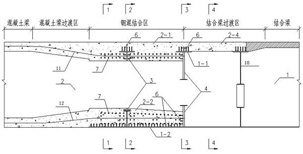
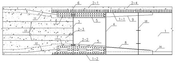
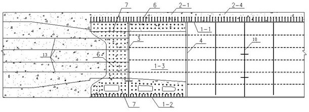
[0042] Such as Figure 1~7 As shown, a steel-concrete combined section structure of a large-span hybrid combined beam for a high-speed railway includes an open steel box girder 1, a concrete bridge deck 2-4 and a concrete box girder 2, and the steel girder floor at the bottom of the open steel box girder 1 The free ends of 1-2 form the steel beam nozzle plate 1-5, the steel beam bottom plate 1-2, the steel beam nozzle plate 1-5 outsourcing the concrete box girder 2, the steel beam middle web of the open steel box girder 1 1-3 and steel girder side webs 1-4 are embedded in concrete box girder 2 to realize the combination of open steel box girder 1 and concrete box girder 2.

[0043] A steel beam top plate 1-1 is arranged on the top of the steel beam middle web 1-3 and the steel beam side web 1-4.

[0044] The concrete bridge deck 2-4 is combined with the open st...


PUM


Abstract

Disclosed is a steel-concrete combined section structure of a large-span hybrid combined beam of a high-speed railway. The steel-concrete combined section structure comprises an open steel box girder, a concrete bridge deck and a concrete box girder, a steel beam tuyere plate is formed at the free end of a steel beam bottom plate at the bottom of the open steel box girder, and the steel beam bottom plate and the steel beam tuyere plate wrap the concrete box girder. A steel beam middle web plate and a steel beam side web plate of the open steel box beam are embedded into the concrete box beam, and combination of the open steel box beam and the concrete box beam is achieved. Concrete is poured on a top plate, a bottom plate and a web plate on the side span concrete beam side of the front bearing plate, concrete is poured on the top plate and the bottom plate between the front bearing plate and the rear bearing plate, concrete is poured only on the top plate on the middle span combination beam side of the rear bearing plate, and heightening transition stiffening ribs are arranged on the combination beam. Through graded transition and thickness change of concrete of the top plate, the bottom plate and the web, smooth rigidity transition between the concrete beam and the composite beam is achieved, and the composite beam is particularly suitable for a high-speed railway large-span composite composite beam with the high requirement for riding comfort.

Description

technical field [0001] The invention belongs to the technical field of bridge engineering, and in particular relates to a steel-concrete combined section structure of a large-span mixed combined beam of a high-speed railway. Background technique [0002] The steel-concrete combination section realizes the reliable connection between the steel beam and the concrete beam, and maintains the overall stress and coordinated deformation of the main beam. The combined section transmits the relatively large stress of the steel beam to the concrete beam evenly and smoothly through the pressure-bearing plate to bear the pressure or through the connector to bear the shear. The joint section usually includes the steel beam transition area, the steel-concrete joint area and the concrete beam transition area. The rationality and coordination of the three parts have an important impact on the function of the joint section. As the span of the bridge increases, the internal force of the stee...

Claims


Application Information

Patent Timeline
IPC IPC(8): E01D19/00E01D19/12E01D2/04E01D101/20E01D101/30
CPCE01D2/04E01D19/00E01D19/125E01D2101/24E01D2101/30
Inventor 苏伟王淑敏谢远超马广宋威张悦牟兆祥季伟强邢继胜张素杰
Owner CHINA RAILWAY DESIGN GRP CO LTD
Learn More