
Carbon-free sintering method for providing heat by adopting high air temperature

A carbon sintering and heat technology, applied in the field of blast furnace ironmaking, can solve problems such as uncontrollable sintering process

Pending Publication Date: 2021-05-18
ANHUI UNIVERSITY OF TECHNOLOGY
View PDF7 Cites 0 Cited by
  • Summary
  • Abstract
  • Description
  • Claims
  • Application Information

AI Technical Summary

Problems solved by technology

[0008] The purpose of the present invention is to solve the problem of using coke powder and coal powder as fuel to provide heat in the current sinter production process, thereby producing a large amount of CO 2 , SO 2 And pollutants such as nitrogen oxides, and the sintering process cannot be controlled, providing a carbon-free sintering method that uses high wind temperature to provide heat

Method used


Image

  • Carbon-free sintering method for providing heat by adopting high air temperature

Examples


Embodiment 1

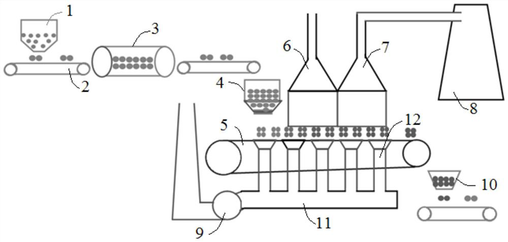
[0061] In this embodiment, a carbon-free sintering method that uses high wind temperature to provide heat, the specific steps are: weigh the raw materials in each sintering raw material bin 1 according to the set amount, discharge them on the feeding belt 2, and then put each The raw materials in the sintering raw material bin 1 are transferred to the cylindrical mixer 3 to form a mixture with a particle size of 10 mm, and then loaded into the mixing bin 4; then the bottom material is laid on the sintering trolley 5, and the bottom material adopts a particle size of 10mm, 20mm thick and fuel-free sintered ore, and then uniformly distributed along the height direction of the trolley, the thickness of the material layer is 800mm; Internal combustion forms high-temperature gas, and enters the high-temperature hot-air hood 7 and the low-temperature hot-air hood 6 through the pipeline, and controls the temperature of the high-temperature gas in the flue gas furnace 8 so that the tem...

Embodiment 2

[0063] A carbon-free sintering method using high wind temperature to provide heat in this embodiment, its specific steps are the same as in Example 1, the difference is that: the particle size of the mixture is 5mm; the bottom material used when laying the bottom material The particle size is 20mm, and the thickness is 40mm; the thickness of the material layer during the cloth is 700mm; the temperature of the hot air in the high-temperature hot-air cover 7 is 1300°C; the temperature of the hot-air in the low-temperature hot-air cover 6 is 800°C.

Embodiment 3

[0065] A carbon-free sintering method using high wind temperature to provide heat in this embodiment, its specific steps are the same as in Example 1, the difference is that: the particle size of the mixture is 8mm; the bottom material used when laying the bottom material The particle size is 15mm, and the thickness is 30mm; the thickness of the material layer is 750mm; the temperature of the hot air in the high temperature hot air cover 7 is 1330°C; the temperature of the hot air in the low temperature hot air cover 6 is 820°C.


PUM


Abstract

The invention discloses a carbon-free sintering method for providing heat by adopting high air temperature, and belongs to the technical field of blast furnace ironmaking. The carbon-free sintering method is carried out on a sintering trolley; a plurality of hot air hoods are correspondingly arranged above the sintering trolley; the hot air hoods are communicated with a flue gas furnace through pipelines; after material distribution on the sintering trolley is completed, the sintering trolley is started, and hot air is provided for the hot air hoods through the flue gas furnace; and then hot air in the hot air hoods penetrates through the sintering trolley through an exhaust fan below the sintering trolley, sintering heat is provided through high hot air of the flue gas furnace, and sintering is carried out. By the adoption of the technical scheme, the problem of environmental pollution during sinter production can be effectively solved, emission of pollutants in the sintering process is greatly reduced while the requirement for the normal production yield is met, the hot air temperature is controllable, the sintering process is convenient to control, and practicability is good.

Description

technical field [0001] The invention belongs to the technical field of blast furnace ironmaking, and more specifically relates to a carbonless sintering method using high blast temperature to provide heat. Background technique [0002] The iron and steel industry is a large energy consumer, and it is also a source of industrial dust, solid waste, CO 2 , SO 2 The main source of pollutants such as nitrogen oxides and nitrogen oxides. CO produced by coking and sintering in the long process of blast furnace ironmaking-converter steelmaking 2 , SO 2 Exhaust gases such as nitrogen oxides, smoke and dust are the most serious, among which the sintering process produces the most exhaust gases, especially the sulfur dioxide produced accounts for 70% of the entire process, and also produces pollutants such as dioxins and fluorides. As the national environmental protection requirements become more and more stringent, the task of reducing emissions in the sintering process will becom...

Claims


Application Information

Patent Timeline
IPC IPC(8): C22B1/22
CPCC22B1/22
Inventor 吴宏亮杨佳龙程旺生张正好李家新杨建温宝良常生朝尤胜强曹恒
Owner ANHUI UNIVERSITY OF TECHNOLOGY
Learn More