Dry sludge receiving and conveying process and sludge drying system thereof

A sludge drying and sludge drying technology, which is applied in dewatering/drying/concentrating sludge treatment, incinerators, degassed water/sewage treatment, etc., can solve problems such as increased labor intensity, environmental pollution, and damage to human health.

Pending Publication Date: 2021-05-18
浙江景顺循环科技有限公司
View PDF0 Cites 5 Cited by
  • Summary
  • Abstract
  • Description
  • Claims
  • Application Information

AI Technical Summary

Problems solved by technology

[0004] The purpose of the present invention is to provide a dry sludge receiving and conveying process and its sludge drying system, so as to solve the existing sludge drying system proposed in the above-mentioned background technology. After the sludge is thickened, it is necessary to use physical methods to further reduce the water content of the sludge, so as to facilitate the transportation, accumulation, utilization or further treatment of the sludge. Drying of land with good leakage is more often done in artificial drying bed to deal with the water inside it, but such a treatment method will not only pollute the land to a certain extent, but also It needs to be collected and moved again, which seriously increases the labor intensity and labor cost, and in the process of natural drying, the discharged water cannot be used for treatment, and the special sludge may even contain heavy metals elements, which will cause serious pollution to the environment and directly damage human health

Method used


Image

  • Dry sludge receiving and conveying process and sludge drying system thereof
  • Dry sludge receiving and conveying process and sludge drying system thereof
  • Dry sludge receiving and conveying process and sludge drying system thereof

Examples


Embodiment Construction

[0027] The technical solutions in the embodiments of the present invention will be clearly and completely described below with reference to the accompanying drawings in the embodiments of the present invention. Obviously, the described embodiments are only a part of the embodiments of the present invention, but not all of the embodiments. Based on the embodiments of the present invention, all other embodiments obtained by those of ordinary skill in the art without creative efforts shall fall within the protection scope of the present invention.

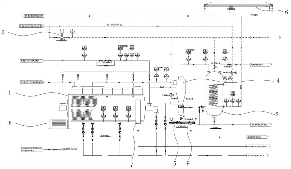
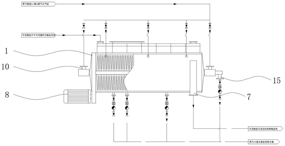
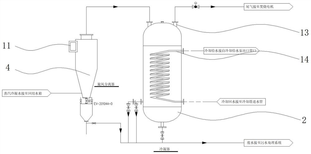
[0028] see Figure 1-5 , The present invention provides a technical solution: a dry sludge receiving and conveying process and a sludge drying system thereof, including a disc dryer 1, a condenser 2, a reverse cleaning pump 3, a cyclone separator 4, and a dust conveyor 5 , workshop crane 6, sludge outlet 7, drive motor 8, auger fan blade 9, steam inlet 10, separator inlet 11, dust residue discharge port 12, exhaust gas outlet 13, cond...


PUM


Abstract

The invention relates to a dry sludge receiving and conveying process and a sludge drying system thereof. The sludge drying system comprises a disc dryer and a condenser, wherein steam inlets are formed in the two sides of the outer wall of the disc dryer, a sludge outlet is formed in one side of the outer wall of the disc dryer, a steam condensation outlet is formed in one side of the outer wall of each steam inlet, and a driving motor is arranged on one side of the outer wall of the disc dryer. Compared with the prior art, the process and the system have the following beneficial effects that sludge and sewage are separated in the disc dryer to dry the sludge so as to conveniently discharge the sludge, and the sewage is separated and enters the cyclone separator firstly, so that wastewater, dust and waste gas are separated respectively; and particle impurities in the sewage are removed, the sewage with dust filtered out is conveyed into the condenser, waste gas in the sewage is volatilized and connected to the incineration fan to be utilized and treated, and the rest of the sewage is output from the lower end to be subjected to stage treatment.

Description

technical field [0001] The invention relates to the technical field of sludge drying treatment, in particular to a dry sludge receiving and conveying process and a sludge drying system thereof. Background technique [0002] Sludge drying, also known as sludge dewatering, refers to the process of removing most of the water content from sludge through infiltration or evaporation, generally referring to the use of self-evaporation facilities such as sludge drying fields. After the sludge is concentrated, the moisture content of the sludge is further reduced by physical methods, which is convenient for the transportation, accumulation, utilization or further treatment of the sludge. There are two kinds of dehydration (drying), natural evaporation method and mechanical dehydration method. It is customary to call the mechanical dehydration method as sludge dehydration, and the natural evaporation method as sludge drying. Although the methods are different, they are all measures ...

Claims


Application Information

Patent Timeline
Patent Type & Authority Applications(China)
IPC IPC(8): C02F11/13C02F1/20C02F1/38F23G7/00F23G7/06F28B1/02
CPCC02F1/20C02F1/38C02F11/13F23G7/001F23G7/06F28B1/02
Inventor 薄一峰陈小敏
Owner 浙江景顺循环科技有限公司
Why Eureka
Try Eureka