
Toggle rod type injection molding machine mold closing mechanism

A mold clamping mechanism and injection molding machine technology, applied in the field of polymer material machinery, can solve problems such as large frictional resistance, single material, and inability to fully lubricate guide sleeves

Pending Publication Date: 2021-05-18
TEDERIC MACHINERY
View PDF0 Cites 0 Cited by
  • Summary
  • Abstract
  • Description
  • Claims
  • Application Information

AI Technical Summary

Problems solved by technology

However, the material of the existing mold shifting guide sleeve is single, and its wear resistance is not good. The inner surface of the guide sleeve body is only provided with concentric grooves, so that the lubricating oil cannot fully lubricate the contact surface of the guide sleeve and the tie rod in the circumferential direction of the tie rod, and friction occurs during the linear motion. The resistance is large, and it is difficult to avoid the surface wear and fracture of the tie rod

Method used


Image

  • Toggle rod type injection molding machine mold closing mechanism
  • Toggle rod type injection molding machine mold closing mechanism
  • Toggle rod type injection molding machine mold closing mechanism

Examples


Embodiment Construction

[0017] The present invention will be further described below in conjunction with the accompanying drawings and specific embodiments.

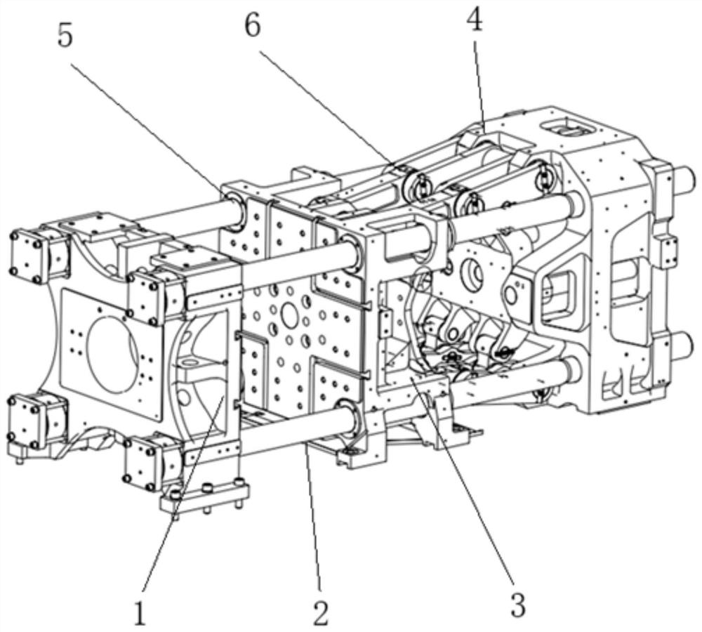
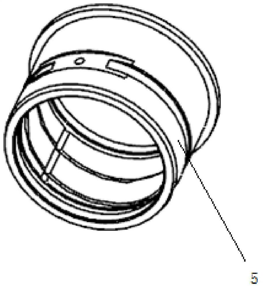
[0018] The clamping mechanism of the toggle type injection molding machine of the present invention, such as figure 1 As shown, in addition to the front template 1, the movable template 3, the rear template 4, the toggle mechanism 6 and the four pull rods 2 included in the mold clamping mechanism of the existing toggle-type injection molding machine, the toggle-type injection molding machine is closed Die mechanism also includes a kind of mold shifting guide sleeve 5, and mold shifting guide sleeve 5 is installed in the two ends of four tie rod holes of movable formwork. In the mold clamping mechanism of the existing toggle-type injection molding machine, the mold is installed between the front template 1 and the movable template 3, the toggle mechanism 6 is installed between the movable template 3 and the rear template 4, and the mold adjustme...


PUM

PropertyMeasurementUnit
thicknessaaaaaaaaaa

Abstract

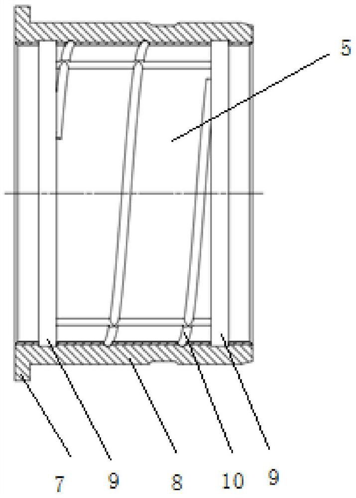
The invention discloses a toggle rod type injection molding machine mold closing mechanism which comprises a mold moving guide sleeve on the basis of an existing toggle rod type injection molding machine mold closing mechanism. The mold moving guide sleeve comprises a guide sleeve body and a flange, the mold moving guide sleeve is made of a steel-clad copper material, and the inner surface of the guide sleeve adopts a structural form of concentric grooves and spiral grooves. The mold moving guide sleeve body is of a cylindrical structure, the flange is arranged on the outer side of one end of the guide sleeve body, and when the guide sleeve body is matched with a movable mold plate, the flange is 3-4 mm higher than an outer hole of the guide sleeve body in the radial direction, consumables are reduced, cost is reduced, and meanwhile waste in the machining process is avoided. The outer layer of the mold moving guide sleeve is made of a steel-clad copper material made of tin bronze on the inner wall of 20# carbon structural steel, and the wear resistance is improved due to the steel-clad copper structure. Compared with an existing mold moving guide sleeve of a single concentric groove structure, the concentric groove and spiral groove structure can improve the guide effect on lubricating oil, the lubricating oil is more evenly distributed in the circumferential direction of a pull rod, lubrication is more sufficient, the abrasion resistance of moving parts is improved, abrasion is reduced, and the maintenance cost is reduced.

Description

technical field [0001] The invention relates to the field of polymer material machinery, in particular to a mold clamping mechanism of a toggle-type injection molding machine. Background technique [0002] When the injection molding motorized template is opened and closed, it needs to do reciprocating linear motion on the tie rod. If the lubrication is not in place, the mold shifting guide sleeve will have hard friction with the tie rod, which will cause the chrome plating layer on the surface of the tie rod to wear out, and if it is serious, it will cause the tie rod to break. Therefore, a reasonable and effective mold shifting guide sleeve is very important. At present, the mold-moving guide sleeve commonly used in the injection molding machine industry is an interference fit with the hole of the movable template tie rod. It is installed in the hole of the movable template tie rod through pre-freezing, and the mold-moving guide sleeve is fixed on the movable template tie r...

Claims


Application Information

Patent Timeline
Patent Type & Authority Applications(China)
IPC IPC(8): B29C45/83B29C45/64
CPCB29C45/83B29C45/64
Inventor 郑建国周宏伟魏建鸿申增强饶忠邵水铭赵望奇
Owner TEDERIC MACHINERY
Learn More