
Inverter control method, switching tube driving circuit, controller and inverter

A technology of drive circuit and control method, which is applied in the direction of control/adjustment system, instrument, electrical components, etc., can solve the problems of reduced operating efficiency of the inverter, increased voltage stress and loss of the switch tube, and slow turn-off speed, etc., to achieve reduction The effect of current change rate, reduction of turn-off loss, and reduction of commutation speed

Active Publication Date: 2021-05-14
SUNGROW POWER SUPPLY CO LTD
View PDF4 Cites 0 Cited by
  • Summary
  • Abstract
  • Description
  • Claims
  • Application Information

AI Technical Summary

Problems solved by technology

If during the commutation process, the speed of commutation from the power diode to the switch tube is too fast, resulting in a large current change rate on the power diode, which will cause the voltage stress of the power diode to exceed the standard, and the voltage stress will be superimposed on the commutation. On the switch tube, the voltage stress and loss of the switch tube increase. Especially in the case of low current, the turn-off characteristics of the power diode are relatively hard (that is, the turn-off speed is slow). In this case, the voltage stress of the power diode exceeds the standard. serious
[0003] The traditional solution is to use soft recovery diodes. This type of diode has a slow turn-off speed and soft characteristics, so as to reduce the current change rate of the diode. However, the loss of the soft recovery diode is high, which leads to the inverter running Reduced efficiency

Method used


Image

  • Inverter control method, switching tube driving circuit, controller and inverter
  • Inverter control method, switching tube driving circuit, controller and inverter
  • Inverter control method, switching tube driving circuit, controller and inverter

Examples


Embodiment Construction

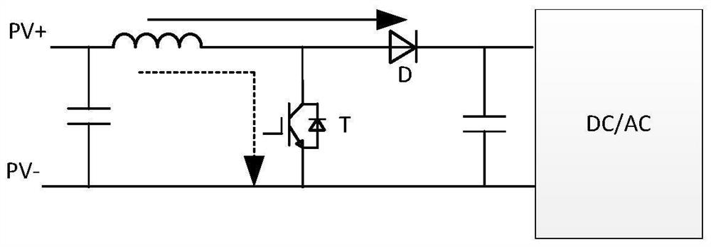
[0060] See figure 1 , shows a topology diagram of a two-level Boost inverter, such as figure 1 As shown, the function of the diode D is freewheeling, specifically, when the switch tube T is turned off, the diode D is freewheeling. When the switch tube T is turned on, the diode D commutates to the switch tube T, and the diode D is turned off. In the process of researching the present invention, the inventor found that in the process of commutating the diode to the switch tube, due to the short turn-on time of the switch tube T, the problem of excessive current change rate is likely to occur during the turn-off process of the diode D, and at the same time , the stress of the diode will be superimposed on the switch tube T, resulting in increased stress and loss of the switch tube. Moreover, when the operating current of the inverter is small, the stress of the diode is more serious.

[0061] Therefore, in order to solve the technical problem that the stress of the diode excee...


PUM


Abstract

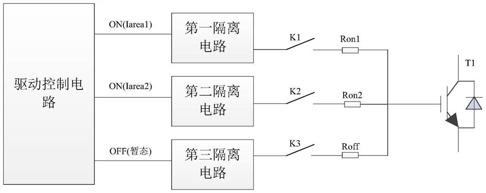
The invention provides an inverter control method, a switching tube driving circuit, a controller and an inverter, according to the scheme, in the process of converting a current from a power diode to a switching tube of the inverter, the switching tube is controlled to be conducted with different resistance values according to different running currents of the inverter, specifically, as the current value of the inverter is gradually reduced, the conduction resistance of the switching tube is gradually increased, so that the conduction speed of the switching tube is reduced, namely the commutation speed is reduced, the current change rate of the power diode during commutation is further reduced, and the reverse stress at the two ends of the power diode is finally reduced. Moreover, when the current of the inverter is large, the resistance value of the on-resistor of the switching tube is small, the switching-on loss of the switching tube and the switching-off loss of the power diode are reduced, so that the operation efficiency of the inverter is high.

Description

technical field [0001] The invention belongs to the technical field of power electronics, and in particular relates to an inverter control method, a switch tube drive circuit, a controller and an inverter. Background technique [0002] The working principle of the inverter is to convert direct current into alternating current by controlling semiconductor tubes. In an inverter, a power diode and a switch tube are usually provided, and the power diode is mainly used in a boost circuit or an inverter circuit to provide a commutation circuit for the switch tube. If during the commutation process, the speed of commutation from the power diode to the switch tube is too fast, resulting in a large current change rate on the power diode, and then causing the voltage stress of the power diode to exceed the standard, and the voltage stress will be superimposed on the commutation. On the switch tube, the voltage stress and loss of the switch tube increase, especially in the case of low...

Claims


Application Information

Patent Timeline
IPC IPC(8): H02M1/08H02M7/537H02M3/156
CPCH02M1/08H02M7/537H02M3/156Y02B70/10
Inventor 赵仁明朱万平
Owner SUNGROW POWER SUPPLY CO LTD
Learn More