Main circuit topology of artificial zero-crossing technology and current transfer method

A main circuit and current technology, applied in the direction of circuits, electric switches, electrical components, etc., can solve the problems that the inductance of the coil does not increase significantly, slow down the speed of current reduction, and increase the magnetic permeability, so as to improve the reliability of large current breaking performance, increase inductance, and reduce the effect of current change rate

Active Publication Date: 2018-03-23
WUHAN MARINE ELECTRIC PROPULSION RES INST CHINA SHIPBUILDING IND CORP NO 712 INST
View PDF10 Cites 0 Cited by
  • Summary
  • Abstract
  • Description
  • Claims
  • Application Information

AI Technical Summary

Problems solved by technology

However, due to the hysteresis characteristic of the actual iron core, it will demagnetize along the hysteresis loop during the decrease of the current of the coil Ls, and the magnetic permeability near the zero point of the current cannot be significantly increased, and the coil inductance does not increase significantly. The saturable reactor cannot significantly slow down the current reduction speed before the mechanical switch current crosses zero, and can only realize the limitation of the current reduction speed after the current zero crosses, such as Figure 5 shown
Saturable reactors that can effectively reduce the rate of change of current before the current zero point need to be specially designed, and the volume is very large

Method used


Image

  • Main circuit topology of artificial zero-crossing technology and current transfer method
  • Main circuit topology of artificial zero-crossing technology and current transfer method
  • Main circuit topology of artificial zero-crossing technology and current transfer method

Examples


Embodiment Construction

[0019] The present invention will be described in further detail below in conjunction with the accompanying drawings.

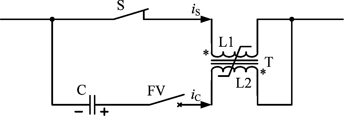
[0020] refer to image 3 As shown, the present invention discloses a main circuit topology of artificial zero-crossing technology, including a parallel main current path and a current transfer circuit. The main current path is composed of a mechanical switch S and a primary coil L1 of a saturated transformer T in series. The current transfer circuit is composed of a pre-charging capacitor C, a control switch FV and the secondary coil L2 of the saturated transformer T in series. The connection terminal of the capacitor C and the mechanical switch S is the pre-charging negative pole.

[0021] The primary coil L1 of the saturated transformer T and the current direction of the same terminal of the secondary coil L2 are opposite, and the turns ratio of the primary coil L1 and the secondary coil L2 is N1:N2, wherein N1>N2, the saturation The transformer T starts t...


PUM


Abstract

The invention discloses a main circuit topology of an artificial zero-crossing technology, comprising a main current path and a current transfer circuit connected in parallel, wherein the main currentpath is formed by a mechanical switch S and a primary coil L1 of a saturation transformer T connected in series. The current transfer circuit consists of a pre-charging capacitor C, a control switchFV and a secondary winding L2 of the saturation transformer T which are connected in series. The connection terminal of the capacitor C with the mechanical switch S is a pre-charging negative electrode. The present invention also discloses a current transfer method thereof. The primary coil and the secondary coil of the saturation transformer T have opposite excitation magnetic potential directions during the current transfer process, and can quickly exit the saturation state before the current zero crossing of the mechanical switch S, so that the inductance of the transfer circuit is significantly increased. The current change rate near the current zero point of the mechanical switch S is reduced, and the high current breaking reliability of the mechanical switch S is improved.

Description

technical field [0001] The invention belongs to the technical field of circuit breakers, and in particular relates to a main circuit topology based on artificial zero-crossing technology and a current transfer method thereof. Background technique [0002] A typical circuit breaker technical solution based on manual zero-crossing technology is as follows: figure 1 As shown, the reverse high-frequency current provided by the LC current transfer circuit is superimposed on the short-circuit current in the main mechanical switch S to quickly generate a zero-crossing point of the current, and realize the rapid breaking of the circuit. Especially for DC current breaking, using artificial zero-crossing technology can quickly and effectively manufacture DC current zero-crossing points. Due to the simple and mature technology, it is an important development direction for medium and high voltage DC circuit breakers. [0003] In order to realize the rapid zero-crossing of the main mech...

Claims


Application Information

Patent Timeline
IPC IPC(8): H01H9/56
CPCH01H9/56
Inventor 彭振东任志刚杨晨光涂煜骆文平
Owner WUHAN MARINE ELECTRIC PROPULSION RES INST CHINA SHIPBUILDING IND CORP NO 712 INST
Why Eureka
Try Eureka