An optical fiber combiner and splitter
A fiber combiner and fiber combining technology, applied in the field of lasers, can solve the problems of violating the development trend of fiber lasers, increasing the complexity of fiber laser wiring and integration, and increasing the number of devices, so as to improve the synthesis efficiency, simplify the layout, The effect of suppressing the rate of temperature rise
- Summary
- Abstract
- Description
- Claims
- Application Information
AI Technical Summary
Problems solved by technology
Method used
Image

Examples
Embodiment 1
[0028] like Figure 4 As shown, a fiber combiner and splitter, using In terms of application effect, the laser beams in P input fibers 1 are synthesized and then distributed to M output fibers 2, which is equivalent to integrating multiple fiber combiners to reduce the number of optical components .
[0029] Specifically, the optical fiber combiner and splitter are regarded as integrating M type structure fiber combiner, with root input fiber 1, M output fiber 2, by using In the cross-section of the fiber bundle composed of two input fibers, the outer ring can accommodate more fibers than the inner ring. Compared with the original The fiber optic combiner can greatly reduce the equivalent tapering ratio of the optical fiber, improve the combining efficiency, and reduce the loss of optical devices. Among them, , the fiber combiner has P 1 One input fiber and one output fiber.
[0030] In addition, the fiber combiner and splitter have the functions of combining and ...
Embodiment 2
[0034] like Figure 5 As shown, the same parts of this embodiment and Embodiment 1 will not be repeated, and the difference is:
[0035] The number of optical fiber combiners and splitters is set to 2, and the post-stage cascaded fiber bundler of the fiber optic combiner and splitter adopts type structure, the number of input pump fibers of the fiber bundler . Since the optical fiber combiner and splitter integrates M Type structure fiber combiner, with Root input optical fiber, M root output optical fiber, that is to say, the quantity of described output optical fiber and The number of fiber-optic combiners of the type structure is equal. At the same time, P 1 There is no specific requirement, it can be an integer or a non-integer number, that is, the ratio of the number of input optical fibers and output optical fibers of the optical fiber combiner and splitter is not necessarily an integer.
Embodiment 3
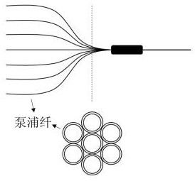
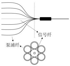
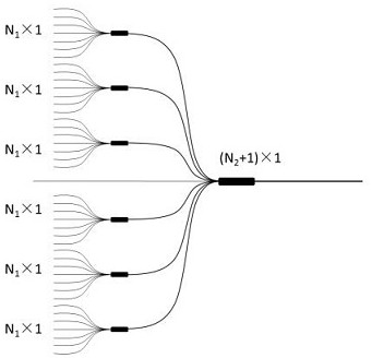
[0037] In the current scientific research and industrial lasers commonly used Pump combiner cascade Pump signal Cluster structure as an example (such as image 3 shown), treat the fiber combiner as a combination of 3 A fiber combiner (equivalent to a pump combiner) forms fiber optic combiners and splitters (such as Figure 4 shown), then image 3 The shown structure transforms into Figure 5 In the structure shown, the total number of optical devices is reduced by four. at the same time, Figure 4 Compared to figure 1 and figure 2 , only one more turn of the input fiber is arranged on the cross-section of the input fiber 1, that is, the cross-sectional area of the input fiber 1 is slightly larger than the prior art, but, Figure 4 However, the total number of optical devices is significantly reduced, and at the same time, the synthesis loss and photothermal energy can be effectively reduced.
[0038] set up The beam combiner and splitter also use input fiber...
PUM
| Property | Measurement | Unit |
|---|---|---|
| diameter | aaaaa | aaaaa |
Abstract
Description
Claims
Application Information
 - Generate Ideas
- Intellectual Property
- Life Sciences
- Materials
- Tech Scout
- Unparalleled Data Quality
- Higher Quality Content
- 60% Fewer Hallucinations
Browse by: Latest US Patents, China's latest patents, Technical Efficacy Thesaurus, Application Domain, Technology Topic, Popular Technical Reports.
© 2025 PatSnap. All rights reserved.Legal|Privacy policy|Modern Slavery Act Transparency Statement|Sitemap|About US| Contact US: help@patsnap.com