
Load applying and testing method for fatigue strength test of piston heat engine

A technology for strength testing and thermal fatigue, which is applied in the testing of mechanical components, testing of machine/structural components, strength characteristics, etc., can solve the problem that the stress field of the piston varies greatly from actual machine, cannot fully reflect the performance of thermal fatigue resistance, and the lack of mechanical load To achieve the effect of flexible application and adjustment, accurate test boundary application and accurate temperature monitoring

Pending Publication Date: 2021-05-14
CHINA NORTH ENGINE INST TIANJIN
View PDF11 Cites 1 Cited by
  • Summary
  • Abstract
  • Description
  • Claims
  • Application Information

AI Technical Summary

Problems solved by technology

The disadvantage is that the piston sample in the thermal fatigue test is in a free state, the thermal deformation of the piston is unconstrained, and the mechanical load on the top of the piston and the pin hole is missing, resulting in a large difference in the stress field of the piston compared with the real machine, especially the high temperature part of the piston. Especially at the mouth, the test results cannot fully reflect its thermal fatigue resistance

Method used


Image

  • Load applying and testing method for fatigue strength test of piston heat engine
  • Load applying and testing method for fatigue strength test of piston heat engine
  • Load applying and testing method for fatigue strength test of piston heat engine

Examples


Embodiment Construction

[0028] It should be noted that, in the case of no conflict, the embodiments of the present invention and the features in the embodiments can be combined with each other.

[0029] In describing the present invention, it should be understood that the terms "center", "longitudinal", "transverse", "upper", "lower", "front", "rear", "left", "right", " The orientations or positional relationships indicated by "vertical", "horizontal", "top", "bottom", "inner" and "outer" are based on the orientations or positional relationships shown in the drawings, and are only for the convenience of describing the present invention and Simplified descriptions, rather than indicating or implying that the device or element referred to must have a particular orientation, be constructed and operate in a particular orientation, and thus should not be construed as limiting the invention. In addition, the terms "first", "second", etc. are used for descriptive purposes only, and should not be understood ...


PUM


Abstract

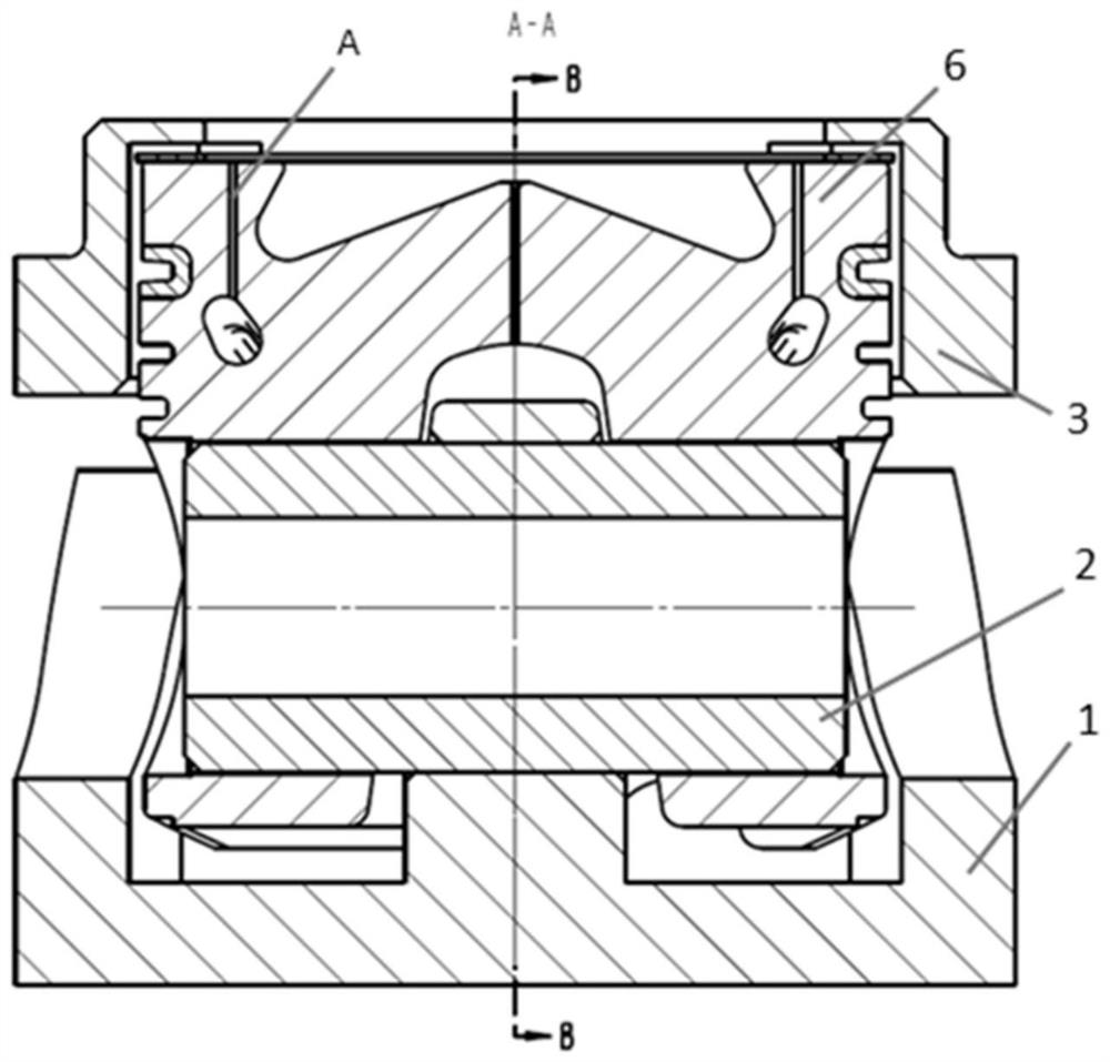
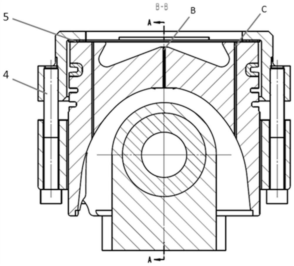
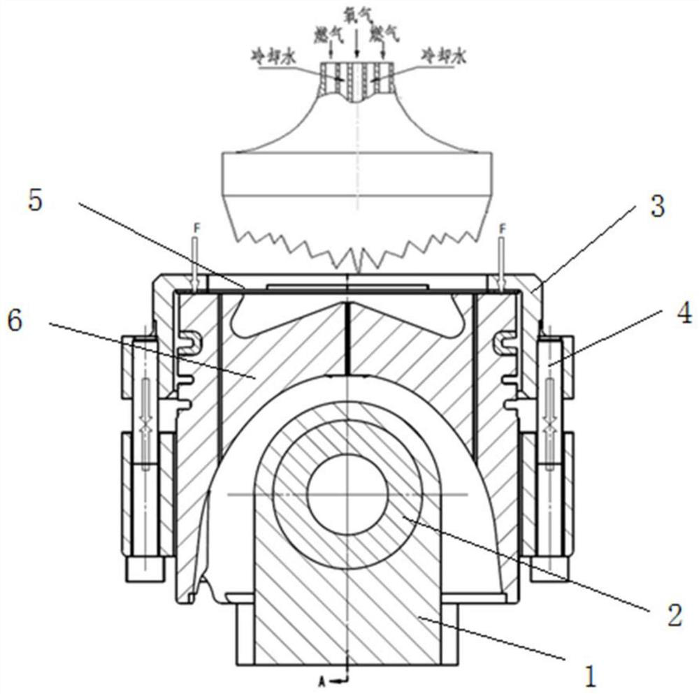
The invention provides a load applying and testing method for a fatigue strength test of a piston heat engine. A piston sample piece and a testing device installed below the piston sample piece are included and the method comprises the following specific testing steps that S1, thermocouples are arranged near a piston combustion chamber throat and at the center of a piston, and the thermocouples are in signal connection with a test control system; S2, non-contact heating is conducted on the head of the piston sample piece in a fuel gas heating mode, a pre-pressing load F is applied to the head area of the piston sample piece 6, and a certain prestress is generated on the combustion chamber throat; and S3, the piston sample piece is forcibly cooled through high-pressure air, and temperature field simulation and high-low temperature conversion of the piston sample piece are achieved. The load applying and testing method has the advantages that mechanical load applying and adjusting are flexible, temperature monitoring of an examination part is accurate, piston combustion chamber throat heat engine coupling stress applying is achieved, and the reliability of a piston engine fatigue strength test result can be effectively improved.

Description

technical field [0001] The invention belongs to the technical field of engine pistons, and in particular relates to a load application and testing method for a piston thermal engine fatigue strength test. Background technique [0002] Component thermal load test is an effective method to evaluate the thermal fatigue strength and reliability of engine pistons, and it is essential in the development of piston products. The thermal fatigue test of piston parts usually adopts electromagnetic induction heating or gas heating to make the surface of the piston combustion chamber reach the predetermined temperature requirement, and then uses high-pressure air to forcibly cool it, so that the piston sample is subjected to alternating thermal loads, and the piston resistance is tested. Thermal fatigue performance. Its advantage is that the thermal load simulation is highly realizable, and the temperature field at the top of the piston is basically consistent with that of the complete...

Claims


Application Information

Patent Timeline
IPC IPC(8): G01M13/00G01N3/60G01N3/32
CPCG01M13/00G01N3/60G01N3/32G01N2203/0073G01N2203/0222
Inventor 王延荣王根全狄建兵侯晔星张丽强
Owner CHINA NORTH ENGINE INST TIANJIN
Learn More