
Heat conduction induction coal-fired boiler flame detector

A technology for flame detectors and coal-fired boilers, applied in combustion chambers, combustion methods, combustion equipment, etc., can solve the problems of easy damage of detection probes, unfavorable operators to monitor furnace combustion conditions, and affect detection results, etc., to achieve good protection performance Effect

Active Publication Date: 2021-05-14
HUANENG SHANDONG POWER GENERATION CO LTD BAIYANGHE POWER PLANT
View PDF10 Cites 0 Cited by
  • Summary
  • Abstract
  • Description
  • Claims
  • Application Information

AI Technical Summary

Problems solved by technology

[0003] During the use of existing flame detectors, the detection probe is a component with high sensitivity, and the lack of corresponding protection mechanism causes the detection probe to be easily damaged. If a protection mechanism is provided, it will protect the probe and make the detection probe not easy It is damaged when it is hit, but there is a large barrier to the detection of the probe, which affects the detection effect. At the same time, in the process of use, the coal powder that is not fully burned in the boiler is easy to accumulate on the outer wall of the detection probe, resulting in the sensitivity of the detection probe. Influence, when the signal is transmitted through the signal transmission optical fiber, the signal strength is easy to jump, which is not conducive to the operator to monitor the combustion situation in the furnace

Method used


Image

  • Heat conduction induction coal-fired boiler flame detector
  • Heat conduction induction coal-fired boiler flame detector
  • Heat conduction induction coal-fired boiler flame detector

Examples


Embodiment 1

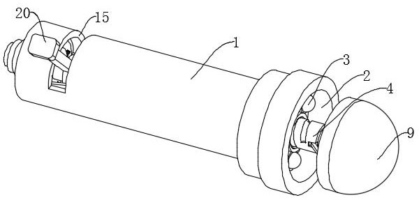
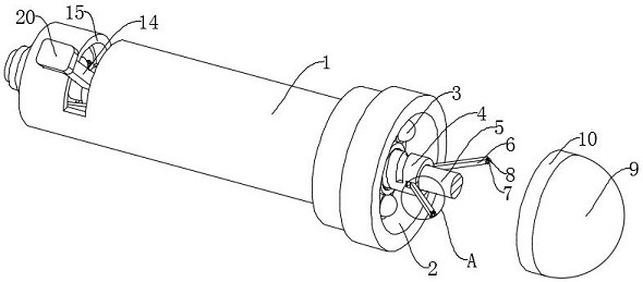
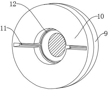
[0035] see Figure 1-7 , a coal-fired boiler flame detector with heat conduction induction, comprising a casing 1 and an induction probe 3, a groove 2 is provided at one end of the casing 1, the induction probe 3 is fixedly connected with the inner bottom surface wall of the groove 2, and the inner bottom surface of the groove 2 The wall is spirally connected with a threaded driving rod 4, and the inside of the threaded driving rod 4 is rotatably connected with a support rod 5. One end of the support rod 5 extends to the outside of the shell 1 and is fixedly connected with a protective cover 9. A chute is provided inside the protective cover 9. Inside the chute Embedded with a sliding post 8, one end of the threaded driving rod 4 is rotatably connected to the first connecting rod 6, the sliding post 8 is rotatably connected to the end of the first connecting rod 6 away from the threaded driving rod 4 through the rotating seat 7, and the inner side of the protective cover 9 is f...


PUM


Abstract

The invention discloses a heat conduction induction coal-fired boiler flame detector. The heat conduction induction coal-fired boiler flame detector disclosed by the present invention comprises a shell and an induction probe, one end of the shell is provided with a groove, the induction probe is fixedly connected with the inner bottom surface wall of the groove, the inner bottom surface wall of the groove is spirally connected with a threaded driving rod, the inner part of the threaded driving rod is rotatably connected with a supporting rod, and one end of the supporting rod extends out of the shell and is fixedly connected with a protective cover. According to the heat conduction induction coal-fired boiler flame detector, the inductive probe is arranged in the groove, so that the inductive probe is not easy to be damaged due to impact, and in the use process of the induction probe, the threaded driving rod is rotated to drive a sliding column to slide into a strip-shaped sliding groove, so that a certain distance is kept between the protective cover and the induction probe, the protective performance is good, meanwhile, the detection of the probe is not blocked, and the detection effect is not influenced; and meanwhile, the protective cover can be stored in the groove, so that cooling water is prevented from entering the induction probe to damage the induction probe during maintenance.

Description

technical field [0001] The invention relates to the technical field of flame detectors, in particular to a heat conduction induction flame detector for a coal-fired boiler. Background technique [0002] The flame detector is an important equipment in the safety monitoring system of the boiler furnace. Its function is to detect the combustion conditions in real time according to the combustion characteristics of the flame. When the fuel supply is stopped when the boiler is extinguished, an alarm can be issued through the alarm system to remind the staff to deal with it in time to ensure the safe operation of the boiler. [0003] During the use of existing flame detectors, the detection probe is a component with high sensitivity, and the lack of corresponding protection mechanism causes the detection probe to be easily damaged. If a protection mechanism is provided, it will protect the probe and make the detection probe not easy It is damaged when it is hit, but there is a la...

Claims


Application Information

Patent Timeline
Patent Type & Authority Applications(China)
IPC IPC(8): F23M11/04
CPCF23M11/045
Inventor 张新城高群翔张其涛张鹏尹震东林旭东
Owner HUANENG SHANDONG POWER GENERATION CO LTD BAIYANGHE POWER PLANT
Learn More