
A fan blade assembly and its motor

A technology of fan blades and components, applied in the direction of electric components, pump components, mechanical equipment, etc., can solve problems such as damage to fan blades, difficulty in installation, fracture and failure of fan blades, etc., to increase dynamic unbalance, reduce the use of tools, and avoid The effect of increased difficulty in processing and disassembly

Active Publication Date: 2022-06-28
GREE ELECTRIC APPLIANCES INC
View PDF13 Cites 0 Cited by
  • Summary
  • Abstract
  • Description
  • Claims
  • Application Information

AI Technical Summary

Problems solved by technology

This kind of installation and fixing method needs to be installed and disassembled with the help of tools such as a hammer. The installation is difficult, and it will cause damage to the extremely thin fan blade itself. A little carelessness will cause the fan blade to break and fail.

Method used


Image

  • A fan blade assembly and its motor
  • A fan blade assembly and its motor
  • A fan blade assembly and its motor

Examples


Embodiment 1

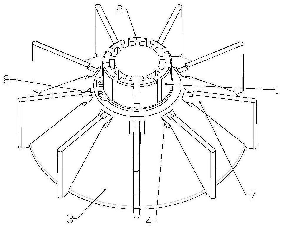
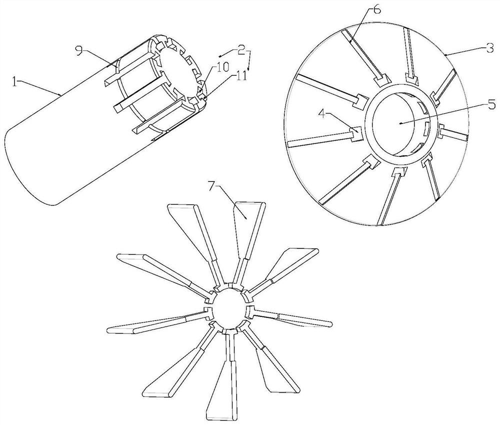
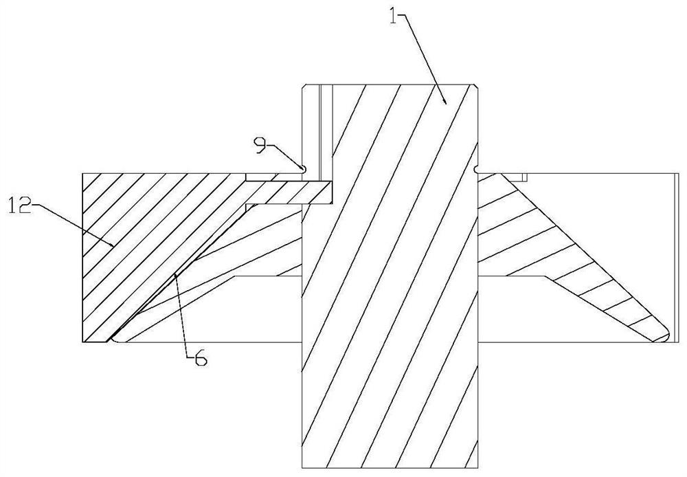
[0024] like Figure 1-2 The illustrated novel fan blade assembly includes: a shaft body 1, the top of the shaft body 1 is provided with an installation keyway 2, and the installation keyway 2 extends from the outside to the inside to the middle of the shaft body 1; The middle part of the air disc 3 is provided with a splicing through hole 5 that is tightly fitted with the shaft body 1; the side end of the air disc 3 is provided with a mounting hole 4, and the mounting hole 4 faces the splicing through hole 5; The blade 7, the fan blade 7 can pass through the installation hole 4 and the installation keyway 2 in sequence, and the wind disc 3 and the shaft body 1 can be detachably connected as a whole.

[0025] In this embodiment, the fan blades can pass through the installation holes in sequence, the installation keyway is detachably connected to the fan plate and the shaft body, which can realize convenient and fast installation and disassembly, and can reduce excessive use of ...


PUM


Abstract

The invention specifically discloses a novel wind blade assembly, which includes: a shaft body, the top of the shaft body is provided with a keyway for installation; a wind pan, the middle part of the wind pan is provided with a splicing through hole that is clamped and matched with the shaft body; The side end of the wind disk is provided with a mounting hole, and the mounting hole is facing the splicing through hole; the fan blade, the fan blade can pass through the mounting hole in turn, the installation keyway and the wind disk and the shaft body can be connected to each other. Disassemble the connection as a whole. The fan blade assembly of the present invention is flexible and convenient to operate, which can reduce excessive use of tools, thereby avoiding the use of tools to cause the blade to break and fail; at the same time, its stability is further improved, and it can also avoid the difficulty of processing and disassembling the fan blade assembly when it is subsequently assembled with the motor increase.

Description

technical field [0001] The invention relates to the technical field of motors, in particular to a fan blade assembly and a motor having the same. Background technique [0002] When the motor is running under operating conditions, the conversion of electrical energy into mechanical energy is realized, and in the process of motor energy conversion, a part of the energy is lost and converted into the form of thermal energy. In order to avoid motor burnout due to untimely heat dissipation, it is necessary to install fan blades on the non-shaft extension end of the motor. The function of the fan blades is to force air convection. When the motor is running, the fan blades rotate with the motor shaft to cool the motor for heat dissipation. , the cooling method of installing the fan blades on the non-shaft extension end of the motor is called the self-fan cooling method of the motor. [0003] However, in the traditional way of fixing the fan blade and the shaft, the fan blade key i...

Claims


Application Information

Patent Timeline
Patent Type & Authority Patents(China)
IPC IPC(8): F04D29/26F04D29/053F04D29/60F04D29/66H02K9/06
CPCF04D29/26F04D29/263F04D29/053F04D29/601F04D29/666F04D29/662F04D29/663H02K9/06
Inventor 韩允梅刘思苑卢素华赖涛韦松沈静文
Owner GREE ELECTRIC APPLIANCES INC
Learn More