
Sand gravel stratum drilling device and drilling process

A drilling device and sand and gravel technology, which is applied in the direction of extracting undisturbed core devices, drill pipes, drill pipes, etc., can solve the problems of unsmooth cuttings removal, cuttings sinking, and prone to sticky drilling, etc., to increase the passing area , High core recovery rate, and the effect of reducing accidents

Active Publication Date: 2021-05-14
TANGSHAN JINSHI SUPER ABRASIVE
View PDF8 Cites 2 Cited by
  • Summary
  • Abstract
  • Description
  • Claims
  • Application Information

AI Technical Summary

Problems solved by technology

First of all, sand and gravel formations are mostly loose, with poor cementation, frequent soft and hard interbeds, and gravel diameters of different sizes. During drilling construction, accidents such as overdiameter, collapse, and drill paste are prone to occur, causing buried drills, stuck drills, etc. during drilling. In-hole accidents such as drill clamping and drill pipe breakage
At present, conventional wireline coring drilling technology is mostly used in sand and gravel formations in China. The outer annular water gap is small, and the chip removal is not smooth, and the cuttings sink to the bottom of the hole, causing secondary breakage; Small, chip removal is not fast, prone to sticky drilling, affecting continuous drilling; during the drilling process, mud skin often occurs on the inner wall of the drill pipe, the inner pipe is blocked when salvaged, the core recovery rate is low, the life of the drill bit is low, and the cartridge assembly Debris is easy to deposit in the recovery tube, which prevents the card from shrinking and causes problems such as failure of salvaging and recovering the core tube.

Method used


Image

  • Sand gravel stratum drilling device and drilling process
  • Sand gravel stratum drilling device and drilling process
  • Sand gravel stratum drilling device and drilling process

Examples


Embodiment Construction

[0034] The present invention will be further described through the embodiments below in conjunction with the accompanying drawings.

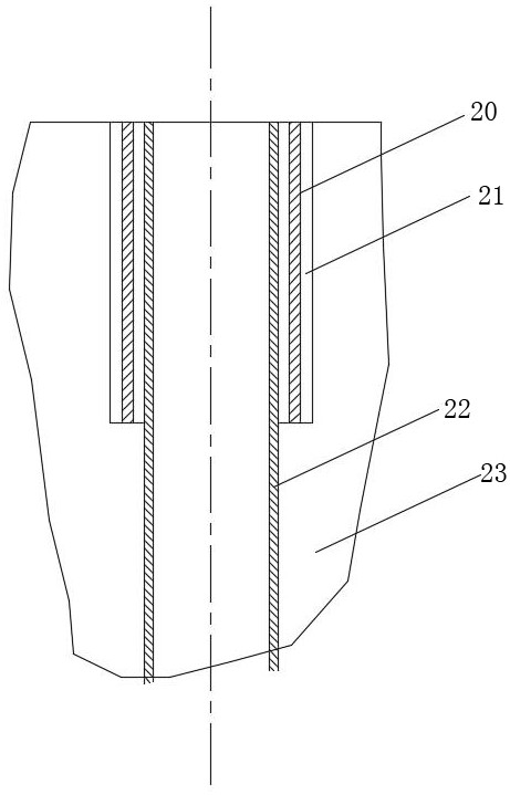
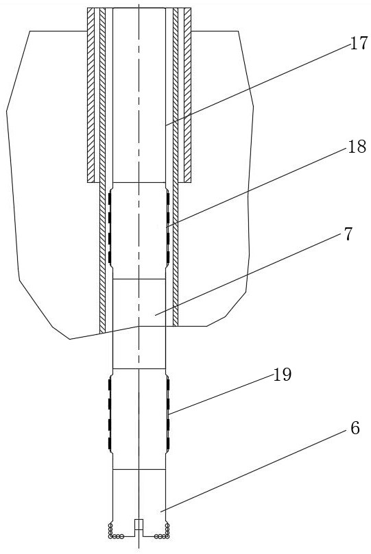
[0035] A sand and gravel formation drilling device, comprising casing one 20, casing two 22, drill pipe 17 and drilling tool 7, casing two 22 is arranged in casing one 20, casing one 20 and casing two 22 and Cement slurry 21 is provided between the sand and gravel formations 23; the drilling tool 7 and the drill pipe 17 are both arranged in the second casing 22, and the top of the drilling tool 7 is connected to the drill pipe 17; the drilling tool 7 includes a cartridge recovery pipe 2. Eject card plate 3, eject card seat 12, adapter 13, suspension joint 14, suspension ring 4, outer pipe 5, inner pipe 8 and centralizer, outer pipe 5 and inner pipe 8 are tubular structures, and the ejector card assembly The recovery pipe 2, the ejection card plate 3, the ejection card seat 12, the adapter 13, the suspension joint 14 and the inner pipe 8 are succ...


PUM


Abstract

The invention relates to a sand gravel stratum drilling device and a drilling process, and belongs to the technical field of geological drilling. According to the technical scheme, a second sleeve (22) is arranged in a first sleeve (20), and cement paste (21) is arranged between the first sleeve (20) and a sand gravel stratum (23) and between the second sleeve (22) and the sand gravel stratum (23); and a drilling tool (7) and a drilling rod (17) are arranged in the second sleeve (22), and the top end of the drilling tool (7) is connected with the drilling rod (17). The sand gravel stratum drilling device and the drilling process have the beneficial effects that the machining precision of the drilling rod is high, dynamic balance is kept in the drilling process, the inner surface and the outer surface of the drilling rod are smooth, rock debris can pass through the drilling rod easily, and the flowing resistance of the rock debris is reduced; a large outer annular gap is formed between the hole wall and an outer pipe of the drilling tool, rock powder is promoted to be rapidly discharged to the ground surface, and the situation that the rock debris is precipitated in a hole, and consequently the accidents of drill sticking and drill burning are caused is prevented; and the drilling efficiency in the sand gravel stratum is improved, the core recovery rate is high, accidents are reduced, and safe drilling is achieved.

Description

technical field [0001] The invention relates to a sand and gravel formation drilling device and a drilling process, belonging to the technical field of geological drilling. Background technique [0002] Conventional wireline coring in sand and gravel formations suffers from a number of construction challenges. First of all, sand and gravel formations are mostly loose, with poor cementation, frequent soft and hard interbeds, and gravel diameters of different sizes. During drilling construction, accidents such as overdiameter, collapse, and drill paste are prone to occur, causing buried drills, stuck drills, etc. during drilling. In-hole accidents such as drill clamping and drill pipe breakage. At present, conventional wireline coring drilling technology is mostly used in sand and gravel formations in China. The outer annular water gap is small, and the chip removal is not smooth, and the cuttings sink to the bottom of the hole, causing secondary breakage; Small, chip remova...

Claims


Application Information

Patent Timeline
IPC IPC(8): E21B17/00E21B17/10E21B17/042E21B21/00E21B10/60E21B25/00E21B33/13
CPCE21B17/00E21B17/1078E21B17/042E21B21/00E21B10/60E21B25/00E21B33/13
Inventor 王久全李婕刘志强王超谷孝宾吴树军
Owner TANGSHAN JINSHI SUPER ABRASIVE
Learn More