Liquid pump

A liquid pump and pump body technology, applied in the field of liquid pumps, can solve the problems of unfavorable environmental protection recycling of POM materials, failure of overall recycling of pump core products, easy cracking of the lower part of the piston, etc., to achieve simple structure, good anti-loosening effect, and stable connection Effect

Pending Publication Date: 2021-05-14
HCP PACKAGING
View PDF0 Cites 1 Cited by
  • Summary
  • Abstract
  • Description
  • Claims
  • Application Information

AI Technical Summary

Problems solved by technology

[0004] 1. In the current pump core, most of the lower valves use glass beads and steel balls. The lower valve and the pump casing need to be assembled separately after injection molding. This not only has a complex structure and low assembly efficiency, but also requires a variety of production materials. The production cost Higher, also causes the problem that the pump core product cannot be recovered as a whole;
[0005] 2. The lower part of the piston is easy to crack after long-term service;
[0006] 3. The head cap connecting rod is made of PP (polypropylene) material, and the piston head is made of POM (polyoxymethylene resin) material, so as to achieve the anti-loosening effect in the cooperation between the head cap connecting rod and the piston head. However, POM material is not conducive to Environmental recycling

Method used


Image

  • Liquid pump
  • Liquid pump
  • Liquid pump

Examples


Embodiment 1

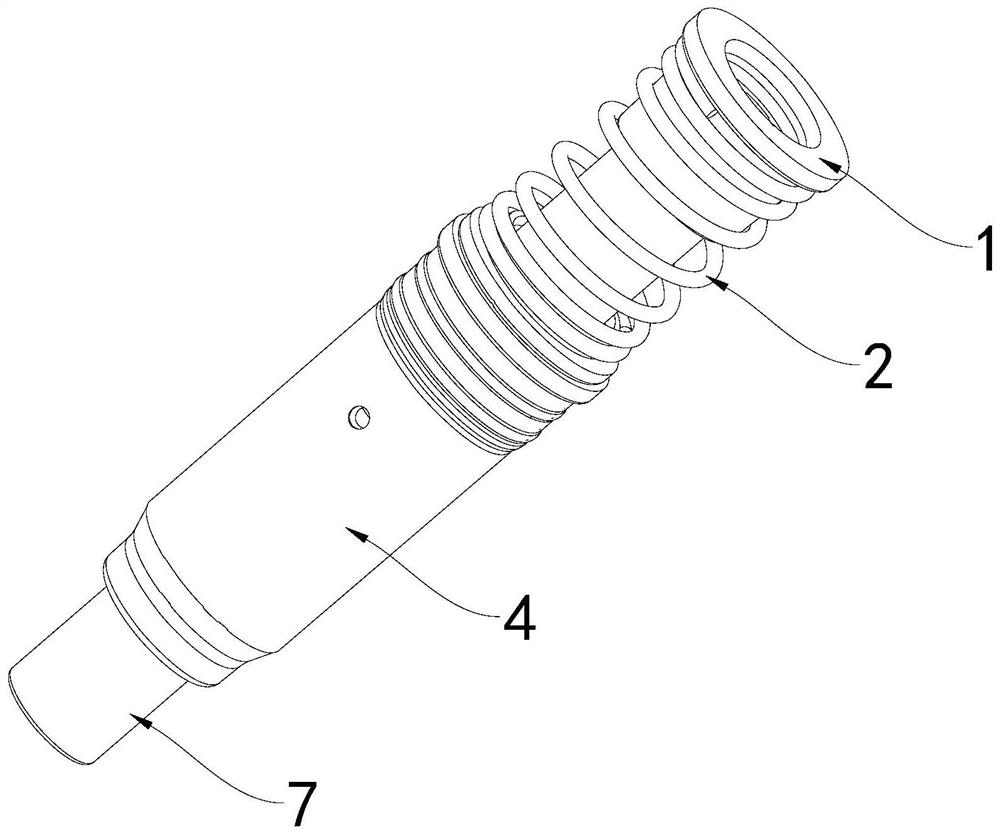
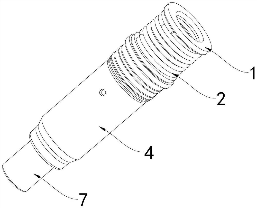
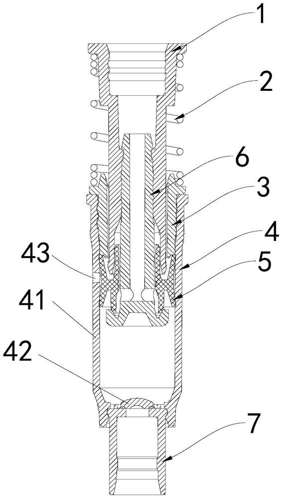
[0056] see Figure 1 to Figure 4 The shown liquid pump includes a connecting rod 1, a spring 2, a lock cover 3, a pump body 4, a piston 5, a piston rod 6, and a valve seat 7, wherein the valve seat 7 is installed on the pump body 4 At the lower end, the lock cover 3 is fixed on the upper end of the pump body 4, the connecting rod 1 and the lock cover 3 are slidingly fitted, the piston rod 6 is fixedly connected with the connecting rod 1, and the piston 5 is slidably sleeved on the piston rod 6, And the piston 5 is slidably arranged in the pump body 4 and sealedly connected with the pump body 4 . see Figure 5 , Figure 6 As shown, the upper end of the connecting rod 1 is fixedly provided with a pressing head cap 8, the pump body 4 is installed in the pump cover 9 of containers such as bottles, and the bottom of the valve seat 7 is fixedly provided with a suction pipe 10 to extend into the container to absorb liquid.

[0057] The detailed structure of the liquid pump is desc...

Embodiment 2

[0083] see Figure 20 to Figure 27 As shown, the main difference between the liquid pump shown in this embodiment and the liquid pump in Embodiment 1 is that the liquid pump in this embodiment is a vacuum pump, and the shell 41 of the pump body 4 does not need to be provided with balancing air holes.

[0084] In summary, the liquid pump of the present invention has a small number of overall parts, which saves production costs, makes product assembly more convenient, and has strong product durability. At the same time, each part of the liquid pump is basically made of recyclable plastics, which can fully recycling.


PUM


Abstract

The invention discloses a liquid pump which at least comprises a pump body and a valve seat. The valve seat is installed at the lower end portion of the pump body, the pump body is an integral part integrally formed by the same material, the pump body comprises a shell with a hollow pump cavity and an elastic valve plate arranged at the bottom end portion of the shell, and the elastic valve plate is provided with a valve channel. The valve seat is arranged below the elastic valve plate in a matched mode, the valve seat comprises a valve body with a liquid flow channel, and the top of the valve body can be matched with the elastic valve plate in a sealed mode. The number of whole components of the liquid pump is small, the production cost is saved, product assembly is more convenient, product durability is high, and meanwhile all components in the liquid pump are basically made of recoverable plastics and can be fully recycled.

Description

technical field [0001] The invention relates to the field of cosmetic packaging containers, in particular to a liquid pump. Background technique [0002] Liquid pumps are widely used in the field of cosmetics to facilitate people's daily life. They are mainly used to pump out liquids in daily cleaning and skin care products such as hand sanitizer, shower gel, shampoo, facial cleanser, and moisturizing liquid. Existing liquid pumps have a variety of structural forms, which usually have pump body, piston rod, piston, head cap connecting rod, spring and other components. When the liquid needs to be pumped out, press the head cap connecting rod downward to make the piston The rod moves down to pump out the liquid pre-stored in the pump body. After the liquid is pumped out, let go of your hand, and under the elastic force of the spring, the piston rod moves upwards, so that the liquid is sealed inside the pump body again, which is very convenient to use. [0003] The liquid pum...

Claims


Application Information

Patent Timeline
Patent Type & Authority Applications(China)
IPC IPC(8): B65D47/34B05B11/00A45D34/00
CPCA45D34/00B05B11/1042B05B11/1001Y02W30/80A45D2200/056B05B11/1074B05B11/1023B05B11/1069B05B11/1047B05B11/0044
Inventor 胡命基
Owner HCP PACKAGING
Why Eureka
Try Eureka