
Reinforcing tube and manufacturing method thereof

A technology of reinforced tubes and composite tubes, applied in the directions of superstructure, superstructure sub-assembly, transportation and packaging, etc., can solve the problem of heavy weight of the reinforced structure of the side beam on the A-pillar, and achieve optimal structural design, light weight, and materials The effect of efficient use

Active Publication Date: 2021-05-14
NINGBO GEELY AUTOMOBILE RES & DEV CO LTD +1
View PDF12 Cites 1 Cited by
  • Summary
  • Abstract
  • Description
  • Claims
  • Application Information

AI Technical Summary

Problems solved by technology

[0005] In order to solve the technical problem that the existing A-pillar upper side beam reinforcement structure is relatively heavy, the present invention proposes a reinforcing tube and a method for manufacturing the reinforcing tube. The present invention is specifically realized by the following technical scheme

Method used


Image

  • Reinforcing tube and manufacturing method thereof
  • Reinforcing tube and manufacturing method thereof
  • Reinforcing tube and manufacturing method thereof

Examples


Embodiment 1

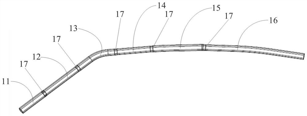
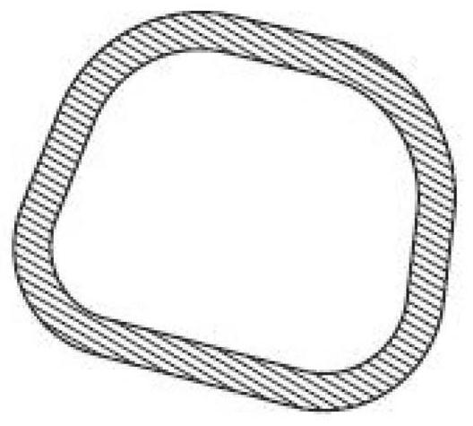
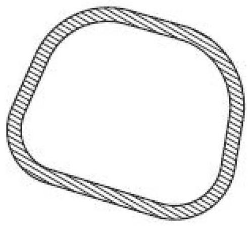
[0036] combine Figure 1 to Figure 4 As shown, the reinforced pipe proposed in Example 1 is a carbon fiber composite pipe, and the reinforced pipe includes a first section 11, a second section 12, a third section 13, a fourth section 14, a fifth section 15 and a sixth section connected in sequence 16. The thickness of the second section 12, the thickness of the fourth section 14 and the thickness of the sixth section 16 are equal, and the thickness of the first section 11, the thickness of the third section 13 and the thickness of the fifth section 15 are all greater than the thickness of the second section 12 The thickness of the reinforcement tube is used to connect the vehicle side wall outer panel and the vehicle side wall inner panel. The third segment 13 in the first embodiment is provided with a curved portion.

[0037] The reinforced pipe in this embodiment 1 is a carbon fiber composite pipe. Compared with the steel pipe in the prior art, it has higher strength and li...

Embodiment 2

[0055] combine Figure 5 As shown, this embodiment 2 provides a method for manufacturing a reinforced tube, which is used to manufacture the reinforced tube in embodiment 1. The method includes:

[0056] Step S101: determining the structural parameters of the reinforcing tube;

[0057] Step S102: adjusting the structure of the mandrel according to the structural parameters;

[0058] Step S103: Perform three-dimensional weaving on the mandrel according to the structural parameters and using carbon fibers to obtain a pre-woven piece;

[0059] Step S104: taking out the mandrel in the pre-woven part and obtaining a prefabricated body;

[0060] Step S105: placing the prefabricated body in the mold, and injecting epoxy resin into the mold;

[0061] Step S106: Perform pressurized heat preservation and curing treatment on the prefabricated body in the mold to obtain a cured tube;

[0062] Step S107: Trimming the cured tube to obtain a reinforced tube.

[0063] In Embodiment 2, th...


PUM

PropertyMeasurementUnit
thicknessaaaaaaaaaa
thicknessaaaaaaaaaa
thicknessaaaaaaaaaa

Abstract

In order to solve the technical problem that an existing A-column upper sidebeam reinforcement structure is large in weight, the invention provides a reinforcing tube and a manufacturing method of the reinforcing tube. The reinforcing tube is a carbon fiber composite tube and comprises a first section, a second section, a third section, a fourth section, a fifth section and a sixth section which are sequentially connected, wherein the thickness of the second section, the thickness of the fourth section and the thickness of the sixth section are equal, and the thickness of the first section, the thickness of the third section and the thickness of the fifth section are all larger than the thickness of the second section. The reinforcing tube is used for connecting a vehicle side wall outer plate and a vehicle side wall inner plate. The reinforcing tube is manufactured through a variable-thickness three-dimensional braiding process, and by fully utilizing the designability of a three-dimensional braided carbon fiber winding technology, the performance is guaranteed, meanwhile, extreme light weight is achieved, and the optimal structural design is achieved. The material thickness of the tubular beam is changed through design at different positions, the material thickness is increased at the main force bearing and connecting positions, and the material thickness is reduced at the secondary force bearing positions, so that the lighter weight is achieved under the same performance as that of a metal reinforcing piece.

Description

technical field [0001] The invention relates to the field of vehicle structures, in particular to a reinforcing pipe and a method for manufacturing the reinforcing pipe. Background technique [0002] In the existing A-pillar upper side beam strengthening scheme, the thickness of the overall tube beam is uniform. Due to the weak high temperature resistance of the cured resin used, it is necessary to adjust the temperature and time of electrophoretic baking in the painting workshop, and the painting workshop needs to be restructured, which is not suitable for the production of the old production line; Get the most weight loss benefits. The commonly used A-pillar reinforcement is high-strength steel. In order to meet the collision safety requirements, multi-layer reinforcement plates are required, which are heavy and not conducive to lightweight. [0003] The existing A-pillar upper side beam reinforcement scheme does not achieve the optimal weight-reducing structural design,...

Claims


Application Information

Patent Timeline
Patent Type & Authority Applications(China)
IPC IPC(8): B62D25/04B62D29/04B29C53/56B29C70/42B29C70/54
CPCB62D25/04B62D29/043B29C53/566B29C70/42B29C70/54
Inventor 吴皓亮史付磊李文中岳力林少辉李振兴马秋
Owner NINGBO GEELY AUTOMOBILE RES & DEV CO LTD
Learn More