Valve apparatus for vehicle

A technology for equipment and vehicles, applied in mechanical equipment, multi-port valves, valve devices, etc., can solve the problems of rapid temperature rise of transmission fluid, deterioration of engine room space utilization, difficult positioning of components, etc., so as to improve overall fuel efficiency, friction and friction. The effect of reduced losses, simplified production and assembly

Pending Publication Date: 2021-05-11
HYUNDAI MOTOR CO LTD +2
View PDF1 Cites 0 Cited by
  • Summary
  • Abstract
  • Description
  • Claims
  • Application Information

AI Technical Summary

Problems solved by technology

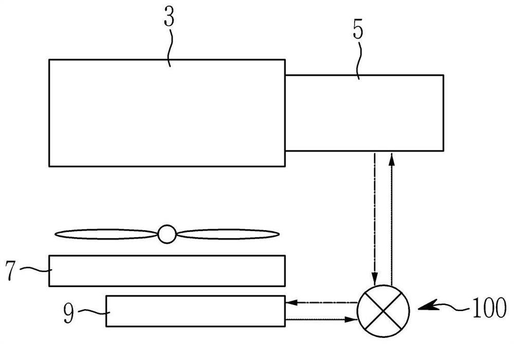
[0007] However, in the bypass valve applied to the conventional transmission fluid cooling system as described above, since each constituent element needs to be sequentially assembled and assembled to the valve mounting hole of the valve housing, there is a disadvantage that it is difficult to precisely position Each constituent element requires excessive assembly time and increases manufacturing cost
[0008] In addition, the bypass valve applied to the transmission fluid cooling system also has the disadvantage that when the transmission fluid does not need to be cooled, due to the low temperature transmission fluid cooled by the oil cooler, a part of the transmission fluid flows from the transmission into the bypass valve and is then in contact with the The bypass transmission fluid in a high temperature state flows into the transmission together, so rapid temperature rise of the transmission fluid is difficult
[0009] In addition, since the conventional bypass valve is located in the flow passage pipe connecting the transmission and the oil cooler, and a relatively large bypass valve is located in the pipe, there is also a disadvantage of deteriorating the space utilization of the engine room

Method used


Image

  • Valve apparatus for vehicle
  • Valve apparatus for vehicle
  • Valve apparatus for vehicle

Examples


Embodiment Construction

[0043] Hereinafter, exemplary embodiments of the present invention will be described in detail with reference to the accompanying drawings.

[0044] The exemplary embodiments disclosed in this specification and the configurations depicted in the drawings are only preferred embodiments of the present invention, and do not cover the entire scope of the present invention. Therefore, it will be understood that various equivalents and modifications may exist in applying the present description.

[0045] To clarify the present invention, parts irrelevant to the description will be omitted, and the same elements or equivalents will be denoted by the same reference numerals throughout the specification.

[0046] Also, the size and thickness of each element are arbitrarily shown in the drawings, but the present invention is not necessarily limited thereto, and in the drawings, the thicknesses of layers, films, panels, regions, etc. are exaggerated for clarity.

[0047] Furthermore, unle...


PUM


Abstract

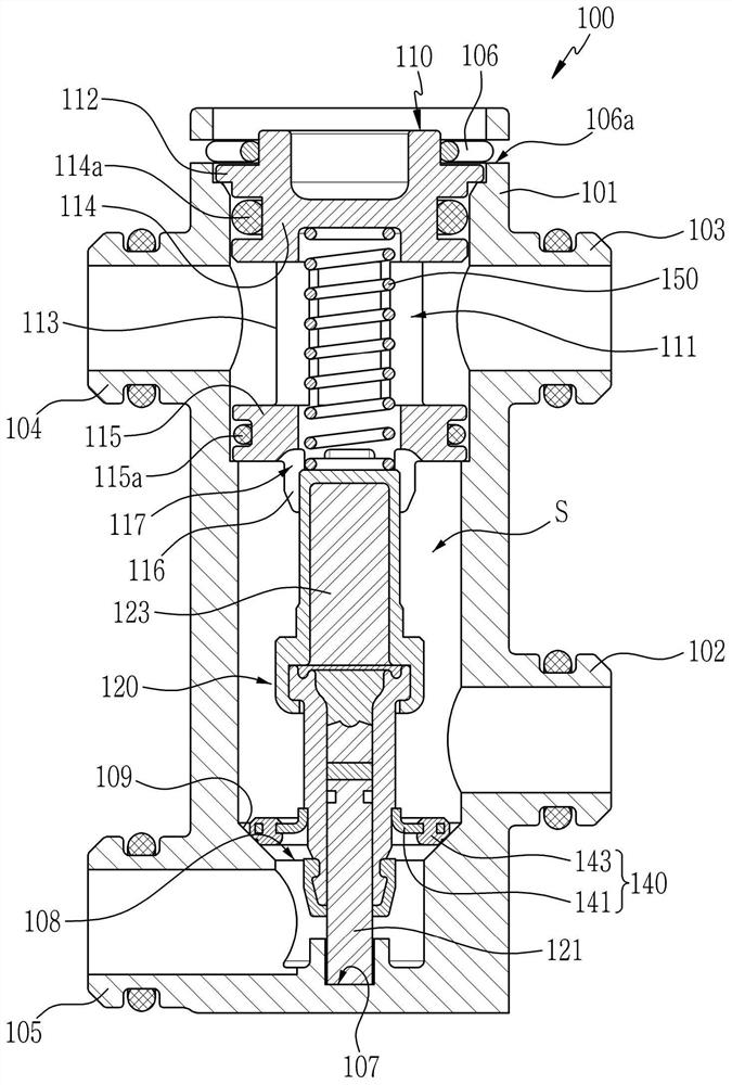
The invention discloses a valve apparatus for a vehicle. The valve apparatus for the vehicle includes a housing having open and closed ends to form an interior space, and formed with first and second intake ports receiving a transmission fluid from a transmission and an oil cooler, a bypass port bypassing the transmission fluid to the transmission, and an exhaust port exhausting the transmission fluid to the oil cooler, an inner cap inserted at least partially into the interior space, fixed to the housing, and having an open hole inserted into the interior space, an operation unit disposed between the inner cap and the closed end of the housing, and reciprocally moves according to a transmission fluid temperature, a valve unit disposed in the operation unit to selectively open and close the bypass port and the exhaust port depending on a movement of the operation unit; and an elastic member interposed between the inner cap and the operation unit.

Description

technical field [0001] The present invention relates to a valve device for a vehicle. Background technique [0002] In general, a valve is a device installed in a pipe or container to allow the inflow of fluids including gases such as air and liquids such as water, and to discharge or prevent the inflow of fluids to the outside, to control the flow of fluids flow rate and pressure. [0003] Typically, such valves are configured to be able to control the flow of fluid by manipulating the valve seat through which the fluid passes using a valve stem and handle, or to be able to be remotely adjusted by sensing the temperature of the fluid flowing through the valve seat using a separate temperature control device. [0004] Meanwhile, in recent years, a valve capable of being controlled according to temperature as described above has been applied to a cooling apparatus for cooling transmission fluid such as transmission oil. [0005] Conventional transmission fluid cooling syste...

Claims


Application Information

Patent Timeline
IPC IPC(8): F16H61/00F15B13/02F16K31/64
CPCF16H61/0009F15B13/02F16K31/002F16K11/044F16H57/0413F16H57/0435F16H57/0412F16H57/0472F16K49/00F16K27/0263
Inventor 金载然长俊豪高赫柱
Owner HYUNDAI MOTOR CO LTD
Why Eureka
Try Eureka