
High-low temperature bending test device for pipe

A technology of high and low temperature test chamber and bending test, which is applied in the direction of applying repetitive force/pulsation force to test the strength of materials, which can solve the problem that it is difficult to simulate the use of TPU pneumatic tubes and cannot well reflect the real performance of TPU pneumatic tubes. and other problems to achieve the effect of improving test efficiency and versatility, controllable test conditions, and ensuring stability and reliability

Active Publication Date: 2021-05-07
SHANGHAI CHANGYUAN ELECTRONICS MATERIAL
View PDF8 Cites 0 Cited by
  • Summary
  • Abstract
  • Description
  • Claims
  • Application Information

AI Technical Summary

Problems solved by technology

However, in the actual use of TPU pneumatic tubes, various conditions do not exist independently, and the existing test methods are static processes, it is difficult to simulate the real use of TPU pneumatic tubes, and cannot well reflect the performance of TPU pneumatic tubes. True Performance of Tubes

Method used


Image

  • High-low temperature bending test device for pipe
  • High-low temperature bending test device for pipe
  • High-low temperature bending test device for pipe

Examples


Embodiment 1

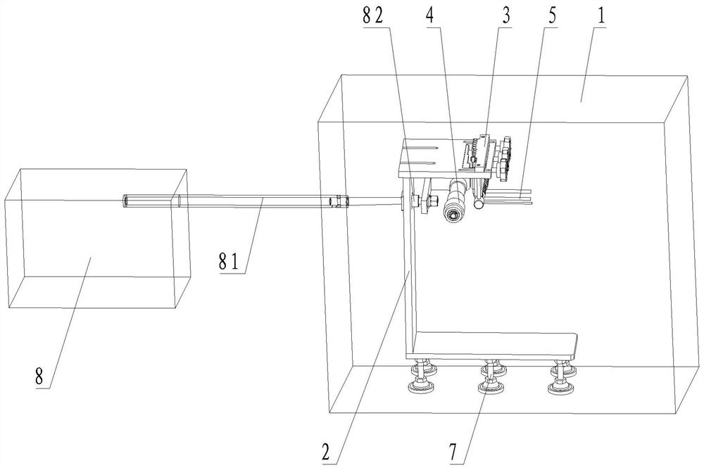
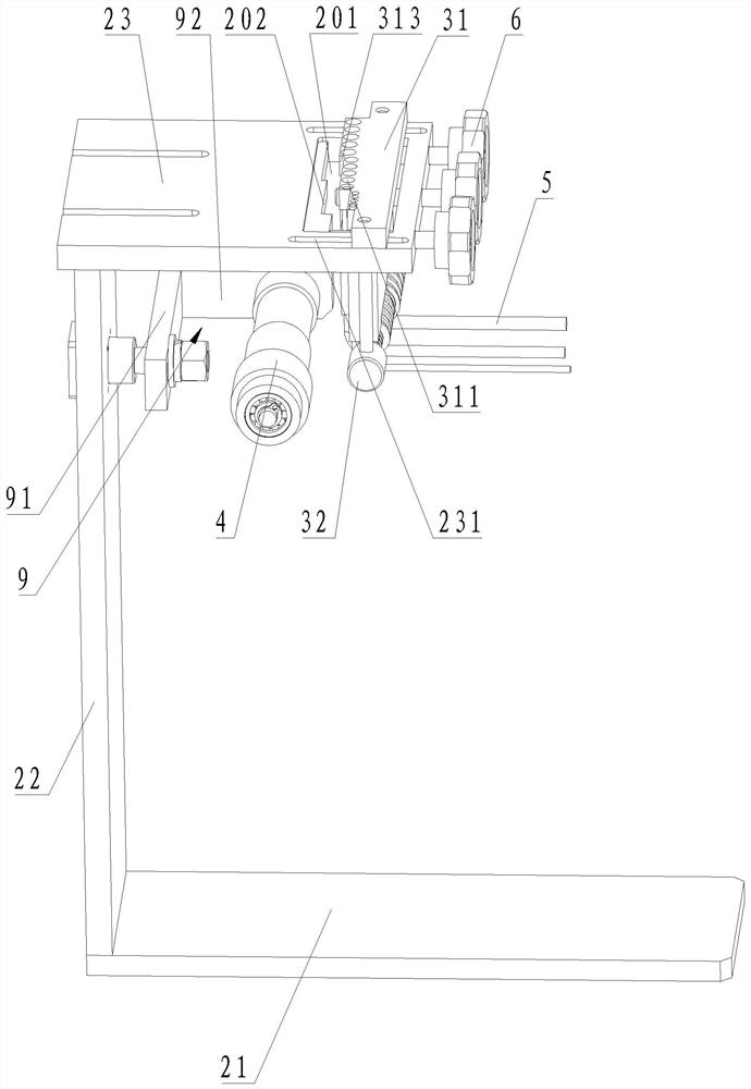
[0044] A high and low temperature bending test device for pipes, such as figure 1 and figure 2 As shown, it includes a high and low temperature test box 1, a support frame 2, a locking pipe fitting 3 and a roller 4. The support frame 2 is arranged in the high and low temperature test chamber 1; the locking pipe fitting 3 is arranged on the support frame 2 for fixing the pipe material 5; 4 is arranged on the support frame 2 and located below the lock pipe 3 , the roller 4 can move back and forth along the first direction, and is used to bend or loosen the pipe 5 protruding from the bottom of the lock pipe 3 .

[0045]Specifically, the high and low temperature test chamber 1 is a casing that can produce high temperature conditions and low temperature conditions. In actual use, a suitable high and low temperature test chamber 1 can be selected according to the high temperature and low temperature required for the test, such as the test conditions of the present invention. The h...

Embodiment 2

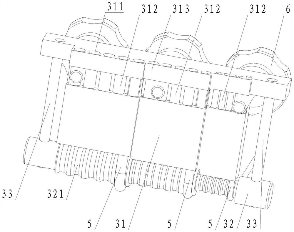
[0062] On the basis of the first embodiment above, as Figure 4 As shown, the guide rod 32 in this embodiment is a multi-stage stepped rod, the roller 4 is a multi-stage stepped roller, and the direction in which the diameter of the guide rod 32 increases in the axial direction is opposite to the direction in which the diameter of the roller 4 increases in the axial direction. The guide rod 32 and the roller 4 are arranged in a multi-step form, so that the roller 4 and the guide rod 32 can simultaneously bend pipes 5 of different diameters to test pipes 5 of different specifications, improving the testing efficiency and versatility of the test device.

[0063] Exemplary, such as Figure 4 As shown, the guide rod 32 includes a first-stage guide rod 322, a second-stage guide rod 323, and a third-stage guide rod 324 whose diameters increase sequentially. Roller 42 and third stage roller 43 , first stage guide rod 322 corresponds to third stage roller 43 , second stage guide rod ...


PUM


Abstract

The invention belongs to the field of pipe testing, and discloses a high-low temperature bending test device for a pipe. The device comprises a high-low temperature test box, a support frame, a lock pipe fitting and rolling wheels; the support frame is arranged in the high-low temperature test box; the lock pipe fitting is arranged on the support frame and used for fixing a pipe; and the rolling wheels are arranged on the support frame and located below the lock pipe fitting, and the rolling wheels can move in a reciprocating mode in the first direction and are used for bending or loosening the pipe stretching out of the bottom of the lock pipe fitting. The high-low temperature cycle test and the bending fatigue test are combined, the testing period is short, the real using performance of the pipe can be reflected, and meanwhile the testing device is controllable in testing condition, easy to operate and stable in testing process.

Description

technical field [0001] The invention relates to the field of pipe testing, in particular to a high-low temperature bending test device for pipes. Background technique [0002] TPU (thermoplastic polyurethane elastomer rubber) pneumatic tubes are widely used in automotive interior parts, and they are the key connectors connecting the lumbar support and the airbag in the car seat. Therefore, there are certain performance requirements for the hardness, blasting performance, bending resistance, aging performance, low temperature performance and fatigue performance of TPU pneumatic tubes. At present, the above-mentioned performances of TPU pneumatic tubes are tested for each single performance through relevant experimental equipment. However, in the actual use of TPU pneumatic tubes, various conditions do not exist independently, and the existing test methods are static processes, it is difficult to simulate the real use of TPU pneumatic tubes, and cannot well reflect the perfor...

Claims


Application Information

Patent Timeline
Patent Type & Authority Applications(China)
IPC IPC(8): G01N3/32
CPCG01N3/32
Inventor 朱晓瑶戴旭阳顾陆於
Owner SHANGHAI CHANGYUAN ELECTRONICS MATERIAL
Learn More