Hydraulic control one-way valve with safety function

A technology of hydraulic control check valve and safety function, which is applied in the direction of safety valve, function valve type, control valve, etc., and can solve the problems of hydraulic control check valve use restriction, simplification, unfavorable system structure, etc.

Pending Publication Date: 2021-05-07
SHANGHAI AEROSPACE CONTROL TECH INST
View PDF8 Cites 0 Cited by
  • Summary
  • Abstract
  • Description
  • Claims
  • Application Information

AI Technical Summary

Problems solved by technology

In some missile weapons, launch vehicles and other hydraulic systems that have strict leakage requirements and very high reliability requirements, the use of the above-mentioned hydraulic control check valves is limited.
[0005] Patent document CN202811589U discloses a hydraulically controlled one-way valve, which belongs to the mechanical field and is mainly used for the height adjustment oil cylinder of the MG400 / 920-WD type electric traction shearer. It includes a valve body, and two one-way valves and two A safety valve, which is characterized in that the liquid inlet and outlet holes of the valve body are arranged on the upper and lower sides of the valve body, the valve body is connected to the liquid plate through a high-pressure rubber hose, and the liquid plate is provided with two connected height adjustment cylinders A One port of each oil passage is provided with a threaded interface for the oil passages in chamber and B chamber, but this design still uses a separate safety valve to realize the safety function, which is not conducive to the simplification of the system structure

Method used


Image

  • Hydraulic control one-way valve with safety function
  • Hydraulic control one-way valve with safety function
  • Hydraulic control one-way valve with safety function

Examples


Embodiment Construction

[0043] The present invention will be described in detail below in conjunction with specific embodiments. The following examples will help those skilled in the art to further understand the present invention, but do not limit the present invention in any form. It should be noted that those skilled in the art can make several changes and improvements without departing from the concept of the present invention. These all belong to the protection scope of the present invention.

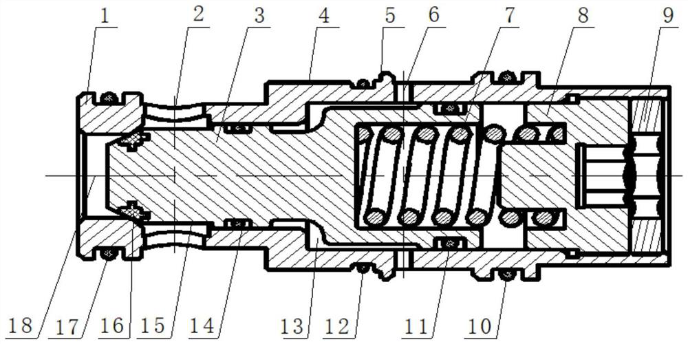
[0044] The invention provides a hydraulic control check valve with safety function, such as figure 1 As shown, it includes a valve body 1, a valve core 3, an elastic body and a base 8. The inside of the valve body 1 is provided with a first accommodating space through both ends, and the valve core 3 is installed in the first accommodating space and Slidingly fit with the inner wall of the valve body 1, the valve core 3 and the valve body 1 preferably adopt a clearance fit, and one end of the valve body ...


PUM


Abstract

The invention provides a hydraulic control one-way valve with a safety function. The hydraulic control one-way valve comprises a valve body, a valve element, an elastic body and a base, a first containing space is formed in the valve body, the valve element is installed in the first containing space, a second containing space is formed between the valve element and the valve body, an oil inlet cavity and an oil outlet cavity are formed in one end of the valve body, the base is installed at the other end of the valve body, the elastic body is arranged between the valve element and the base, and the second containing space communicates with a hydraulic control cavity in the valve body; and the valve element can move between a first position and a second position under driving of external force, when the valve element moves to the first position, the oil inlet cavity communicates with the oil outlet cavity, and when the valve element moves to the second position, the oil inlet cavity does not communicate with the oil outlet cavity. According to the hydraulic control one-way valve, the valve element is of a stepped structure, so that the valve element is opened only under the action of pressure of the oil inlet cavity, thus safety of a system is guaranteed when a control cavity breaks down, the hydraulic control one-way valve has the function of a safety valve, the system structure is simplified, and cost is reduced.

Description

technical field [0001] The invention relates to the technical field of hydraulically controlled one-way valves, in particular to a hydraulically controlled one-way valve with a safety function. Background technique [0002] The hydraulic control check valve is a liquid flow control device in the hydraulic system, which is installed between the high pressure oil circuit and the low pressure oil circuit. When the control chamber is not connected with high-pressure oil, the oil inlet chamber and the oil return chamber are isolated; when the control chamber is connected with high-pressure oil, the oil inlet chamber and the oil return chamber are connected, so that both positive and reverse flow can be controlled. [0003] According to the public information, when the control cavity of the general hydraulic control check valve is blocked from oil and the spool is in the closed state, the hydraulic control check valve will be in a one-way sealing state. It cannot be opened indepe...

Claims


Application Information

Patent Timeline
IPC IPC(8): F16K17/06F16K17/164F16K15/06F16K1/38F16K1/46F16K27/02
CPCF16K17/06F16K17/164F16K15/063F16K1/38F16K1/46F16K27/0254
Inventor 房成李文顶刘洪宇董文勇纪宝亮陈童
Owner SHANGHAI AEROSPACE CONTROL TECH INST
Why Eureka
Try Eureka