
Positioning high-precision cutting and recycling equipment for plastic material processing

A recovery equipment and high-precision technology, which is applied in metal processing and other directions, can solve the problems of inconvenient continuous operation of equipment, inability to automatically control the lifting and lowering of cutting knives, and inconvenient adjustment of plastic materials.

Active Publication Date: 2021-05-07
TAIZHOU YUANDA HOME FURNITURE CO LTD
View PDF8 Cites 0 Cited by
  • Summary
  • Abstract
  • Description
  • Claims
  • Application Information

AI Technical Summary

Problems solved by technology

[0004] After retrieval and analysis, the existing plastic material processing and cutting equipment is inconvenient to adjust the limit of plastic materials. It is often inconvenient to use, and generally the hydraulic rod is used to control the lifting of the cutting knife, which cannot be controlled automatically. The lifting of the cutting knife leads to the fact that the cutting knife is still in the cutting position after the plastic material is cut, which is not convenient for the continuous operation of the equipment. Therefore, further research is required on the basis of the plastic material processing and cutting equipment to provide a plastic material processing tool. Position high-precision cutting and recycling equipment

Method used


Image

  • Positioning high-precision cutting and recycling equipment for plastic material processing
  • Positioning high-precision cutting and recycling equipment for plastic material processing
  • Positioning high-precision cutting and recycling equipment for plastic material processing

Examples


Embodiment Construction

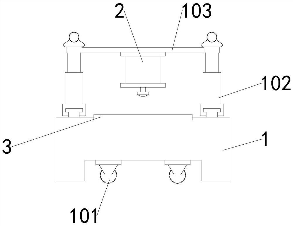
[0030] see Figures 1 to 11 Among them, in an embodiment of the present invention, a positioning high-precision cutting and recycling device for plastic material processing includes: a device body 1, a support column 102 and a top plate 103, and both ends of the top of the device body 1 are equipped with support columns 102, and the two A top plate 103 is installed between the tops of the support columns 102, the bottom of the top plate 103 is provided with a cutting mechanism 2, and the inner top of the equipment body 1 is provided with a limit mechanism 3, and the bottom of the equipment body 1 is equipped with two road wheels 101.

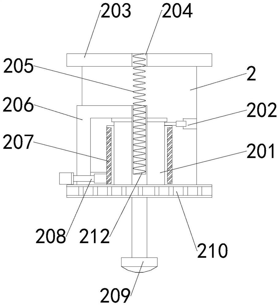
[0031] Wherein, the cutting mechanism 2 includes: a rotating plate 210 and a vertical cylinder 201, the rotating plate 210 is fixedly connected to the bottom of the cutting mechanism 2, and the top of the cutting mechanism 2 is provided with a fixed plate 203, and the middle part of the fixed plate 203 is embedded with a groove 204 , and the gro...


PUM


Abstract

The invention provides positioning high-precision cutting and recycling equipment for plastic material processing. The equipment comprises an equipment body, supporting columns and a top plate, wherein the supporting columns are mounted at the two ends of the top of the equipment body correspondingly, the top plate is mounted between the tops of the two supporting columns, a cutting mechanism is arranged at the bottom of the top plate, a limiting mechanism is arranged at the inner top of the equipment body, an upper movable disc is driven by a second movable shaft to rotate clockwise, limiting plates at the front end and the rear end are forced to move inwards gradually when an inclined first movable groove in the second movable shaft moves, meanwhile, a lower movable disc is driven by a first movable shaft to rotate anticlockwise, when an inclined second movable groove in the first movable shaft moves, limiting plates at the left end and the right end are forced to gradually move inwards, when the four ends of a plastic material are limited, constant force is conveniently applied to the plastic material through gradual clamping of the limiting plates at the four ends, the plastic material is conveniently and automatically leveled and aligned and located in the middle of clamping plates, and the cutting precision is conveniently guaranteed.

Description

technical field [0001] The invention relates to the technical field of plastic material processing, in particular to a positioning high-precision cutting and recycling device for plastic material processing. Background technique [0002] Wood-plastic, that is, wood-plastic composite material, is a new type of composite material that has flourished at home and abroad in recent years. It refers to the use of polyethylene, polypropylene and polyvinyl chloride instead of the usual resin adhesive, and more than 35% -70% Powdered rice husks and straw waste plant fibers are mixed into new wood materials, and then extruded, molded, and injection-molded to produce plates or profiles, which are mainly used in building materials, furniture, and logistics packaging industries. The board is hot-extruded after the powder is mixed in a certain proportion. In the processing of the wood-plastic board, the wood-plastic board needs to be cut into a wood-plastic board of a fixed size; [0003]...

Claims


Application Information

Patent Timeline
IPC IPC(8): B26D7/01B26D7/02B26D7/26B26D7/00B26D7/18
CPCB26D7/01B26D7/025B26D7/2628B26D7/00B26D7/1863B26D7/2614Y02W30/62
Inventor 李开洪
Owner TAIZHOU YUANDA HOME FURNITURE CO LTD
Learn More