Centralized multi-target electric energy quality treatment device

A power quality, multi-objective technology, applied in the direction of circuit devices, harmonic reduction devices, electrical components, etc., can solve the problems of slow response speed of voltage sag dynamic compensation, low efficiency of total battery capacity, difficult maintenance, etc., to solve load Low power factor, easy software implementation, and strong anti-interference performance

Active Publication Date: 2021-05-04
POWERCHINA ZHONGNAN ENG
View PDF6 Cites 0 Cited by
  • Summary
  • Abstract
  • Description
  • Claims
  • Application Information

AI Technical Summary

Problems solved by technology

[0003] For this reason, various power quality compensation devices are installed at the public connection point on the user side of the system power supply (for example, CN108923438A), mainly to control the power quality problems of specific users, subject to the efficiency and economy of the voltage sag control device , rapidity, and device voltage sag compensation capability (compensated voltage sag depth, compensated voltage sag time), etc. The factory-used multi-objective power quality control device is generally placed on the side of the individual load grid, and adopts a decentralized management method. More devices The sub-unit installation leads to low efficiency of total battery capacity and poor economy in power quality management, and also brings many practical problems such as difficult maintenance and poor reliability.
In the prior art, UPS (uninterruptible power supply device) converts AC to DC, stores electrical energy in the battery first, and then provides electrical energy to the load through DC to AC electrical energy conversion. This method adopts The AC-DC mode supplies power to the load, and the efficiency is low; MPC (Multi-function Power Compensation Device) is connected in parallel to the connection point of the load. The battery provides electric energy. This method requires an external power transformer to match the voltage and current of the device. In addition, due to the parallel compensation method, the response speed of the dynamic compensation for voltage sag is relatively slow.

Method used


Image

  • Centralized multi-target electric energy quality treatment device
  • Centralized multi-target electric energy quality treatment device
  • Centralized multi-target electric energy quality treatment device

Examples


Embodiment Construction

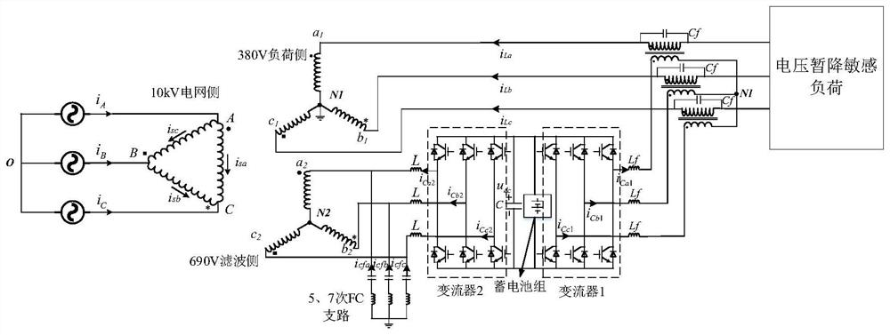
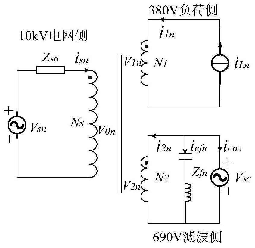
[0032] Such as figure 1As shown, in the topology structure of the embodiment of the present invention, a group of storage batteries are connected in parallel to the middle DC capacitor side of the back-to-back converter to compensate for the lack of electric energy when the load voltage sags, and one end of the back-to-back converter connects the output voltage in series to the power supply line through an isolation transformer To compensate the load voltage sag, the other end is connected to the filter winding of the induction filter transformer by connecting the inductor for the charging of the battery pack connected in parallel on the DC side of the back-to-back converter and the dynamic compensation of load reactive power. The topology structure is used in the filtering of the induction filter transformer The passive filter reactive power compensation branch is connected in parallel in the winding to reduce the demand for reactive power filter compensation capacity of the a...


PUM


Abstract

The invention discloses a centralized multi-target electric energy quality treatment device which comprises a back-to-back converter. And an intermediate direct-current capacitor of the back-to-back converter is connected in parallel with a storage battery pack. According to the invention, through effective multiplexing of the induction filtering transformer, the advantage of filtering reactive compensation of the filtering winding of the induction filtering transformer can be kept and the filtering winding of the induction filtering transformer can be multiplexed to charge the storage battery pack for voltage sag; when voltage sag compensation is performed, the DC voltage of the storage battery is converted into the AC voltage through the isolation transformer and the converter device, and the AC voltage is connected in series and superposed on the load network side voltage. The device has the advantage of rapid voltage compensation response.

Description

technical field [0001] The invention relates to the field of power electronic control, in particular to a centralized multi-objective power quality control device. Background technique [0002] With the continuous and rapid development of industrial technology, electric energy, as an economical, practical, clean and convenient energy source, has become an important basis for economic development and people's life, and users' demand for power electronic equipment is becoming more and more extensive. A large number of non-linear, impulsive, fluctuating and asymmetrical loads have increased synchronously, resulting in a large number of power quality problems such as low power factor, harmonics, and voltage sags. The impact of these problems on the power grid is becoming more and more serious. A low power factor will increase the loss of transmission lines and reduce transmission efficiency; Equipment, and may have local resonance, or even burn electrical equipment; and the pro...

Claims


Application Information

Patent Timeline
IPC IPC(8): H02J3/32H02J3/01H02J3/18H02J3/36
CPCH02J3/32H02J3/01H02J3/1857H02J3/1864H02J3/36Y02E40/30Y02E40/40Y02E60/60
Inventor 王涛彭国荣胡隽璇曾智桢谭崇
Owner POWERCHINA ZHONGNAN ENG
Why Eureka
Try Eureka