Phase shifter and electrically tunable antenna

A phase shifter and phase shifting technology, which is applied in the direction of antenna, antenna grounding switch structure connection, circuit, etc., can solve the problems of high resistance of microstrip line, high requirement of gap, and influence of phase

Active Publication Date: 2021-05-04
COMBA TELECOM TECH (GUANGZHOU) CO LTD +1
View PDF5 Cites 4 Cited by
  • Summary
  • Abstract
  • Description
  • Claims
  • Application Information

AI Technical Summary

Problems solved by technology

[0005] 1. The phase shifter is usually realized by microstrip line coupling. The microstrip line is a semi-open structure. The coupling circuit has high requirements for the gap, and a small gap change will seriously affect the performance of the circuit;
[0006] 2. In order to control the gap between the coupling circuits, the gap will be controlled by introducing a plastic fixed structure, but the plastic fixed structure will cause excessive resistance between the microstrip lines, resulting in the movement of the microstrip line structure during the antenna downturn process A larger pulling force is required, but excessive pulling force will cause the instability of the microstrip line structure, which will affect the phase change again.

Method used


Image

  • Phase shifter and electrically tunable antenna
  • Phase shifter and electrically tunable antenna
  • Phase shifter and electrically tunable antenna

Examples


Embodiment Construction

[0048] Embodiments of the present invention are described in detail below, examples of which are shown in the drawings, wherein the same or similar reference numerals denote the same or similar elements or elements having the same or similar functions throughout. The embodiments described below by referring to the figures are examples, and are only for explaining the present invention and should not be construed as limiting the present invention.

[0049] Those skilled in the art will understand that unless otherwise stated, the singular forms "a", "an", "said" and "the" used herein may also include plural forms. It should be further understood that the word "comprising" used in the description of the present invention refers to the presence of said features, integers, steps, operations, elements and / or components, but does not exclude the presence or addition of one or more other features, integers, steps, operations, elements and / or components, but does not preclude the pres...


PUM


Abstract

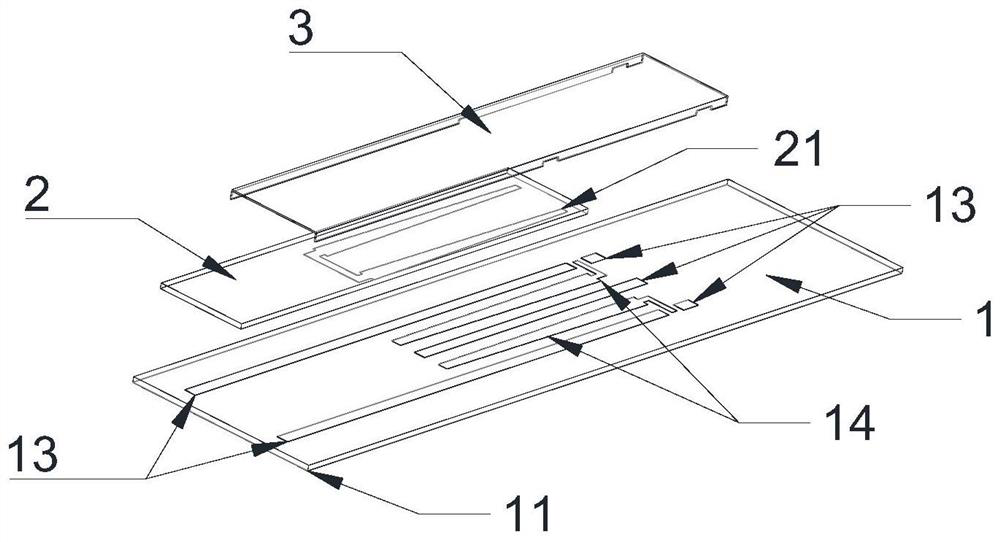
The invention discloses a phase shifter and an electrically tunable antenna, the phase shifter comprises a dielectric component, a phase shifting component and a shielding component, the dielectric component comprises a bottom dielectric plate and a top dielectric plate; the phase shifting component includes two fixed transmission lines arranged on the top face of the bottom layer dielectric plate and arranged side by side in parallel on the two sides of the longitudinal direction of the bottom layer dielectric plate and a phase shifting element arranged on the bottom face of the top layer dielectric plate, and the phase shifting element comprises a transverse strip line and two movable transmission lines which are folded in parallel from the two ends of the transverse strip line in the same direction. The movable transmission lines and the fixed transmission lines are coupled in one-to-one correspondence; the shielding component comprises two coupling lines and a shielding cover, the two coupling lines are arranged side by side and parallel to the two fixed transmission lines correspondingly, and the shielding cover is fixedly connected with the two coupling lines on the two sides of the longitudinal direction to form a shielding cavity for shielding the phase shifting assembly. According to the invention, the shielding cover is welded with the coupling line to form a shielding cavity for accommodating the top dielectric plate, so that the interference of external signals on phase shift is shielded.

Description

technical field [0001] The invention belongs to the technical field of mobile communication, and in particular relates to a phase shifter and an electrically adjustable antenna configured with the phase shifter. Background technique [0002] In mobile communication, the electronically adjustable antenna is one of the key devices, and the phase shifter is the core component of the electronically adjustable antenna. The performance of the phase shifter directly determines the performance of the electronically adjustable antenna, thereby affecting the quality of network coverage, so the importance of the phase shifter in the field of mobile communication is self-evident. [0003] The principle of the phase shifter commonly used in electric antennas is to change the length of the transmission line that is connected to the circuit to change the length of the electrical transmission path that the signal passes through the phase shifter, so as to realize the phase change of the inp...

Claims


Application Information

Patent Timeline
IPC IPC(8): H01P1/18H01Q1/36H01Q1/50H01Q3/32
CPCH01P1/18H01Q1/36H01Q1/50H01Q3/32
Inventor 法斌斌苏国生李明超黄明达陈礼涛
Owner COMBA TELECOM TECH (GUANGZHOU) CO LTD
Why Eureka
Try Eureka