
Valve element structure for improving passing flow

A valve core and flow technology, applied in multi-port valves, valve details, valve devices, etc., can solve the problems of small flow and large reverse resistance, and achieve the effect of reducing reverse resistance and optimizing valve core structure.

Pending Publication Date: 2021-05-04
HYDRAULIK POWER
View PDF0 Cites 0 Cited by
  • Summary
  • Abstract
  • Description
  • Claims
  • Application Information

AI Technical Summary

Problems solved by technology

[0007] The present invention provides a new spool structure for increasing the passing flow. By opening an arc-shaped diversion groove on the sealing end surface of the spool, it solves the problem that not only the flow rate is small but also Technical problems with high reverse resistance

Method used


Image

  • Valve element structure for improving passing flow
  • Valve element structure for improving passing flow
  • Valve element structure for improving passing flow

Examples


Embodiment Construction

[0023] The spool structure for increasing the flow rate according to the present invention can be made of the following materials, and is not limited to the following materials, such as common components such as spool, hydraulic matching system, and electric control device.

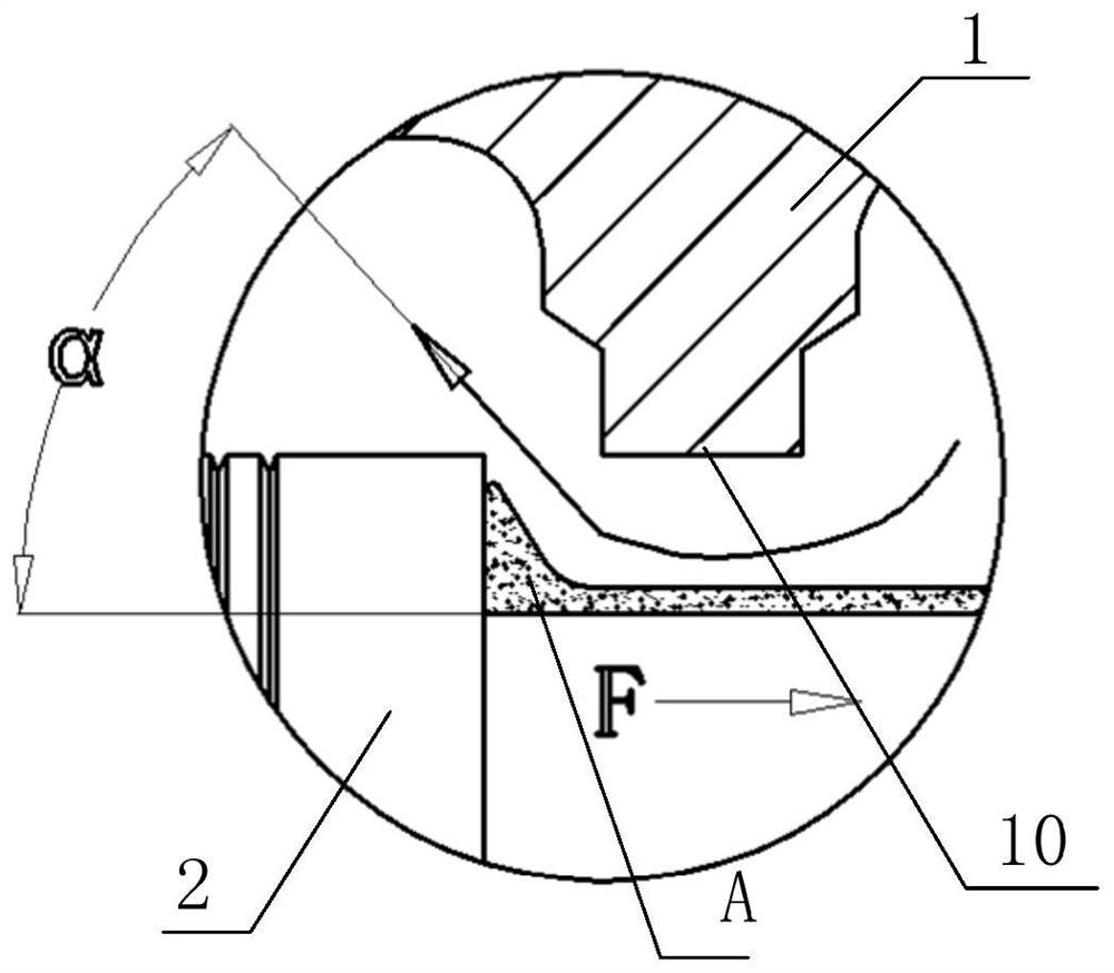
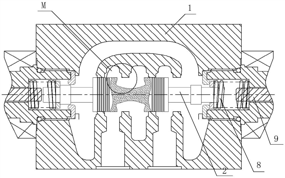
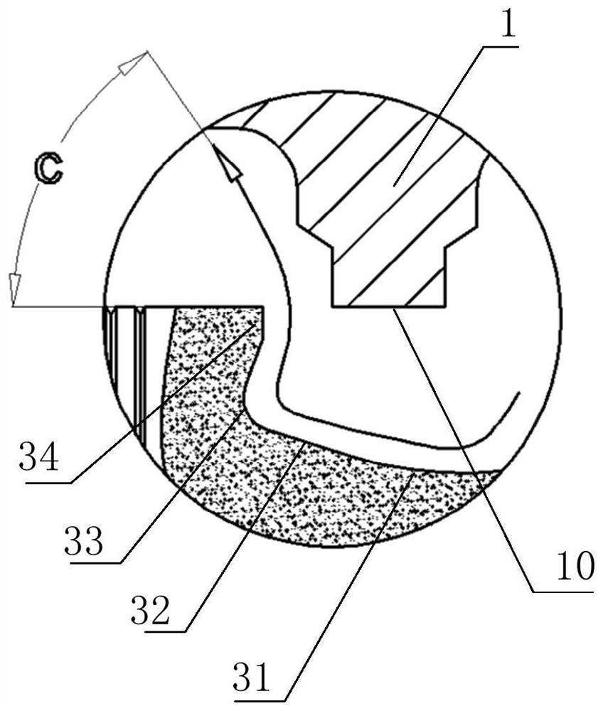
[0024] figure 2 It is a schematic cross-sectional structure diagram of the valve core structure used to increase the flow rate in use according to the embodiment of the present invention; image 3 for figure 2 Partial enlarged schematic diagram of middle M; this embodiment combines Figure 4 Be explained.

[0025] The spool structure for increasing the passing flow in the embodiment of the present invention is an improved structure based on the existing sliding valve structure, and can be applied to any sliding valve structure.

[0026] In the spool structure of this embodiment, the spool 2 is slidably installed in the housing 1, the housing 1 is provided with a high-pressure oil port and at least on...


PUM


Abstract

The invention provides a valve element structure for improving passing flow, and belongs to the field of reversing valve manufacturing. The valve element structure is installed in a shell in a sliding mode, a high-pressure oil port and at least one working oil port are formed in the shell, a sliding hole is formed in the shell, and a valve element is arranged in the sliding hole in a sleeved mode and seals the sliding hole through the radial surface of the valve element. The valve element slides so that a gap can be formed between the axial end surface of the valve element and the sliding hole, and the gap is used for communicating the high-pressure oil port with the working oil port. A concave flow guide groove is formed in the axial end surface of the side, facing the sliding hole, of the valve element, and the bottom of the flow guide groove is provided with a smooth arc-shaped transition curved surface. Under the condition that an opening and a structure of a valve are not changed, by optimizing the valve element structure, under the same pressure drop, more flow can pass through, and the reverse resistance in the opening process of the valve element is effectively reduced.

Description

technical field [0001] The invention relates to valve manufacturing technology, in particular to a valve core structure used to increase flow rate, and belongs to the technical field of hydraulic equipment manufacturing. Background technique [0002] As a hydraulic component to control the on-off and reversing of the oil circuit, the reversing valve is widely used. The common reversing valve is a slide valve structure, and its spool slides in the valve body. By switching the direction of the spool, different oil ports are connected or closed. [0003] The material storage action of the injection molding machine is realized by the oil motor driving the screw to convey the raw material. The rotation of the oil motor is controlled by the reversing valve. Due to the physical characteristics of the raw material and the volume of the raw material to be transmitted, the displacement of the configured oil motor is also different. As a result, the displacement of the pump is also di...

Claims


Application Information

Patent Timeline
Patent Type & Authority Applications(China)
IPC IPC(8): F16K11/065F16K31/06F16N1/00F15B13/02
CPCF16K11/065F16K31/061F16N1/00F15B13/02
Inventor 彭敏陈家豪
Owner HYDRAULIK POWER
Learn More