


Quick Research
Generate reliable direction feasibility study reports for your R&D in just a few steps.

Technical Q&A
Discover and master advanced knowledge NOW. Basics, ideas, possibilities, all at once.

Find Solutions
As an expert in R&D theories, this can generate solutions to your technical problems instantly.

Evaluate Feasibility
Analyze your overall solution with one click, know your potential R&D risks in advance.

Monitor Landscape
Get weekly tech updates, stay abreast of the latest tech innovations and key insights.
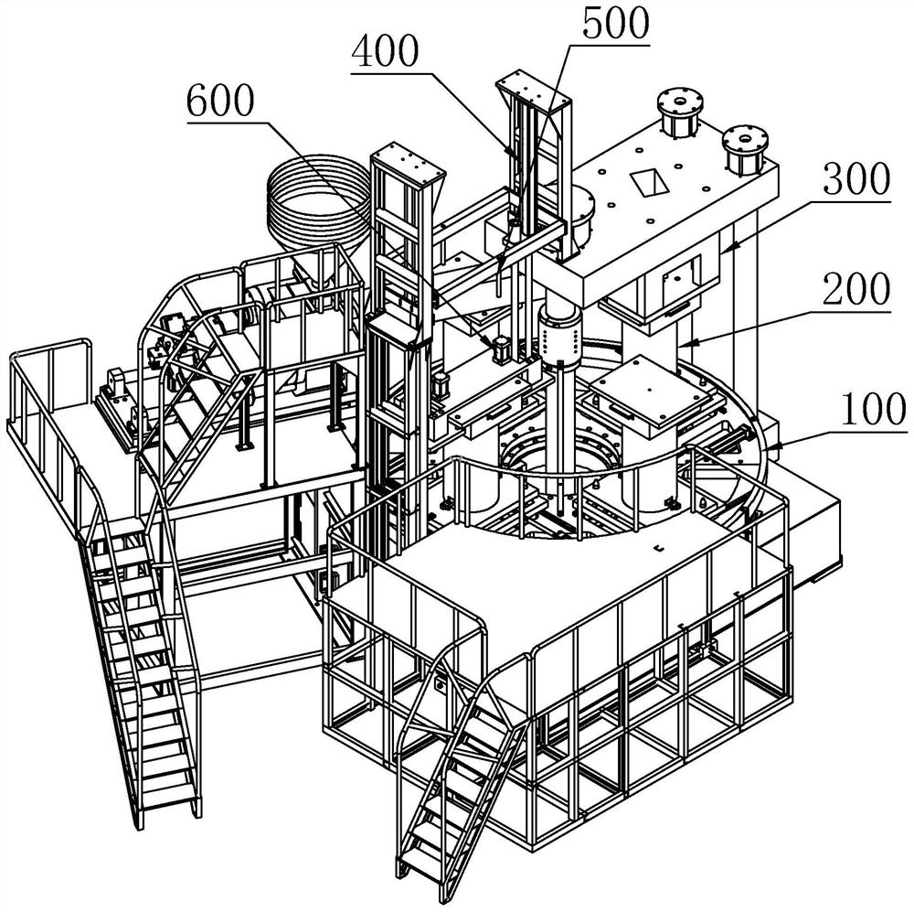
Rotary road cone molding equipment
A rotary road cone technology, applied in the field of rotary road cone plastic molding equipment, can solve problems such as insufficient efficiency
- Summary
- Abstract
- Description
- Claims
- Application Information
AI Technical Summary
Problems solved by technology
Method used
Image

Examples
Embodiment 1
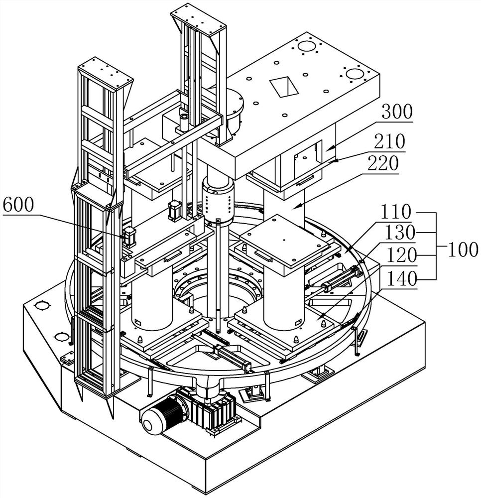
[0030] See attached figure 1 , 2 , 3, 4, 5, 6, 9 A rotary road cone plastic molding equipment, including a transmission mechanism 100, a mold 200 arranged on the transmission mechanism 100, an injection molding mechanism 300 matched with the mold 200, and the transmission mechanism 100 includes a turntable The base 110, the mold holder 120 that is used to install the mold 200 on the turntable base 110, the mold holder 120 is slidably arranged on the turntable base 110, and the turntable base 110 is provided with a driving member 130 that drives the mold holder 120 to slide . A slide rail 140 is provided on the turntable base 110 , and the mold fixing seat 120 is slidably connected to the slide rail 140 . There are three mold fixing seats 120 , which are evenly distributed along the circumferential direction concentrically with the turntable base 110 . The mold 200 includes a cover plate 210 and a lower mold 220 having a cavity matched with the road cone liner 230, the lowe...
Embodiment 2
[0034] refer to figure 1 , 2 , 3, 4, 5, 6, 9, retain the scheme of embodiment one, assemble the road cone liner 230 on the injection molding mechanism 300 instead of assembling with the injection molding mechanism 300, and set another lifting mechanism 400 and take off Die mechanism 500.
[0035] It works as follows:
[0036] The lower mold 220 on the mold holder 120 is injected in the injection molding mechanism 300. After waiting for a short cooling time, the turntable base 110 rotates to drive the mold holder 120 to rotate. The lower mold 220 on the mold holder 120 and the road cone liner 230 are assembled together and enter the cooling state to ensure that the space formed by the road cone liner 230 and the lower mold 220 remains stable to ensure a good molding effect. When the turntable base 110 rotates again, the mold holder 120 enters into the lifting mechanism 400 position, use the lifting mechanism 400 to lift the road cone liner 230, and disassemble it from the l...
Embodiment 3
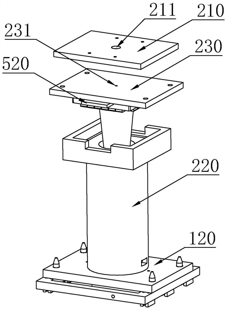
[0038] refer to figure 1 , 2 , 4. Keep the solutions of Embodiments 1 and 2, and design the road cone liner 230 to be provided with an injection flow channel 231 that cooperates with the injection molding mechanism 300, and the injection flow channel 231 is along the cavity opening of the lower mold 220 to The direction of the bottom of the cavity extends and runs through the road cone liner 230 . The cover plate 210 is provided with an injection through hole 211 communicating with the injection channel 231 . The cover plate 210 is assembled with the injection molding mechanism 300 or the cover plate 210 is a part of the injection molding mechanism 300 . Wherein the lower die 220 is a movable die.
[0039] Its working principle is as follows. When the injection molding mechanism 300 needs to be injected, the lower mold 220 is linked with its matching lifting parts, and the lifting parts move the lower mold 220 upwards, so that the lower mold 220 and the cover plate 210 are...
PUM
 Abstract
Description
Claims
Application Information
 - R&D Engineer
- R&D Manager
- IP Professional
- Industry Leading Data Capabilities
- Powerful AI technology
- Patent DNA Extraction
Browse by: Latest US Patents, China's latest patents, Technical Efficacy Thesaurus, Application Domain, Technology Topic, Popular Technical Reports.
© 2024 PatSnap. All rights reserved.Legal|Privacy policy|Modern Slavery Act Transparency Statement|Sitemap|About US| Contact US: help@patsnap.com