Eureka AIR delivers breakthrough ideas for toughest innovation challenges, trusted by R&D personnel around the world.

Mixing and defoaming equipment for water paint processing

A technology for water-based paint and equipment, applied in mixers, mixers with rotary stirring devices, dissolving and other directions, can solve problems such as poor mixing and processing effects of paints, and achieve improved processing efficiency, bubble elimination effect, and bubble elimination. Effect

Inactive Publication Date: 2021-05-04
武汉积墨包装印刷有限公司
View PDF0 Cites 6 Cited by
  • Summary
  • Abstract
  • Description
  • Claims
  • Application Information

AI Technical Summary

Problems solved by technology

[0004] The purpose of the present invention is to solve the problem of poor paint mixing and processing effect in the prior art, and propose a kind of mixing and defoaming equipment for water-based paint processing

Method used


Image

  • Mixing and defoaming equipment for water paint processing
  • Mixing and defoaming equipment for water paint processing
  • Mixing and defoaming equipment for water paint processing

Examples


Embodiment

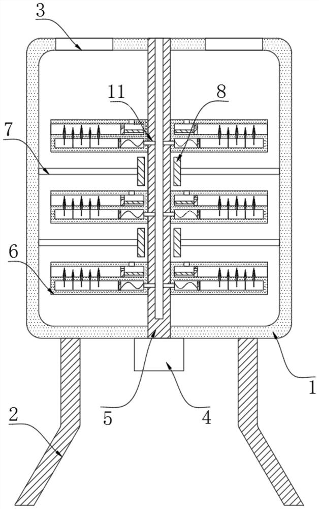
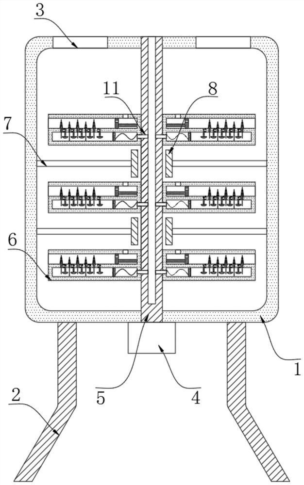
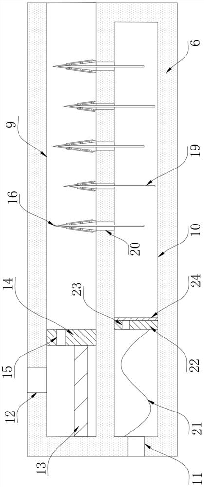
[0023] refer to Figure 1-5 , a mixing and defoaming equipment for water-based paint processing, comprising a stirring box 1, a bracket 2 is fixed on the bottom of the stirring box 1, a discharge port 3 is provided on the upper end of the stirring box 1, a motor 4 is fixed on the bottom of the stirring box 1, and a motor 4 is fixed on the bottom of the stirring box 1. The output shaft of 4 is fixed with a rotating shaft 5, a plurality of stirring blades 6 are fixed on the circumferential side wall of the rotating shaft 5, a plurality of fixed rods 7 are fixed on the inner wall of the stirring box 1, and a magnetic block is fixed at the end of each fixed rod 7 8. The magnetic block 8 is a permanent magnet. The side wall of the stirring blade 6 is provided with a defoaming tank 9. The inside of the defoaming tank 9 is provided with a defoaming mechanism. The inside of the stirring blade 6 is provided with an exhaust chamber 10. The exhaust chamber 10 There is an exhaust mechanis...

Embodiment 2

[0031] The difference between this embodiment and Embodiment 1 is that an air extraction strengthening mechanism is added. The interior of the exhaust chamber 10 is provided with multiple sets of air extraction strengthening mechanisms. The inwall of groove 25 is connected with slide bar 27 by compression spring 26, and the end portion of slide bar 27 is fixed with differential pressure plate 28, and the side wall of slide bar 27 runs through and is provided with discharge hole 29, and the inwall of discharge hole 29 and chute 25 are both A one-way valve is provided, and the sliding rod 27 is sealed and slidingly connected with the inner wall of the chute 25. The inside of the chute 25 is provided with a ventilating liquid barrier film. One side of the pressure difference plate 28 is an arc surface and the other side is a plane. create a pressure difference;

[0032]During the movement of the magnetic fluid, it will quickly pass through the pressure difference plate 28, so tha...


PUM


Abstract

The invention discloses a mixing and defoaming equipment for water paint processing. The mixing and defoaming equipment comprises a stirring box, a support is fixed to the bottom of the stirring box, a discharging opening is formed in the upper end of the stirring box, a motor is fixed to the bottom of the stirring box, a rotating shaft is fixed to an output shaft of the motor, and a plurality of stirring blades are fixed to the circumferential side wall of the rotating shaft; a plurality of fixing rods are fixed to the inner wall of the stirring box, a magnetic block is fixed to the end of each fixing rod, and a bubble removing groove is formed in the side wall of each stirring blade. The equipment has the advantages that by arranging a telescopic rod and the magnetic blocks, in the rotating and stirring process of the stirring blades, the telescopic rod does reciprocating telescopic motion under the action of the magnetic blocks, so that a push plate does reciprocating motion, and raw materials in the center of the stirring box enter the bubble removing groove from the inner inlet and are conveyed to the edge position of the stirring box; the raw materials at the center and the edge positions are exchanged, so that the stirring and mixing effects are improved.

Description

technical field [0001] The invention relates to the technical field of water-based paint, in particular to a mixing and defoaming equipment for water-based paint processing. Background technique [0002] All paints that use water as a solvent or as a dispersion medium can be called water-based paints. Water-based paints include water-soluble, water-diluted, and water-dispersed types; [0003] Water-based paint is a kind of material with high consistency and high viscosity. It is difficult to stir it evenly during mixing, and it is also difficult to ensure high-quality sales in later use. Therefore, the stirring process needs A lot of manpower and material resources are invested, and the existing mixing equipment cannot meet the mixing requirements due to the single mixing structure, and the water-based paint is usually mixed with air bubbles, which needs to be defoamed, which makes the processing efficiency lower and the overall cost higher. Contents of the invention [0...

Claims


Application Information

Patent Timeline
Patent Type & Authority Applications(China)
IPC IPC(8): B01F7/16B01F7/00B01F15/00
CPCB01F27/17B01F27/808B01F35/189B01F2101/30
Inventor 洪俊锋
Owner 武汉积墨包装印刷有限公司
Why Eureka
Eureka Blog
Learn More