
Electric connector applied to vacuum chamber, electrostatic chuck and semiconductor equipment

An electrical connector and vacuum chamber technology, applied in the field of semiconductor equipment, can solve the problems of hard limit, broken ceramic disk, different radial expansion, etc., to avoid excessive stretching, reduce contact resistance, and enhance electrical conductivity. Effect

Active Publication Date: 2021-04-30
BEIJING NAURA MICROELECTRONICS EQUIP CO LTD
View PDF5 Cites 1 Cited by
  • Summary
  • Abstract
  • Description
  • Claims
  • Application Information

AI Technical Summary

Problems solved by technology

However, the space between the ceramic body of the electrostatic chuck and the metal base of the electrostatic chuck is completely closed, and it is impossible to reach into it for wiring. Usually, it is necessary to choose some quick-plug methods for electrical connection
However, the existing radio frequency joints that can realize quick plug-in electrical connection are usually hard contacts, which will place a hard limit on the ceramic disc of the electrostatic chuck and the metal base of the electrostatic chuck, resulting in the two being unable to move relative to each other.
There are usually material differences and temperature differences between the electrostatic chuck ceramic body and the electrostatic chuck metal base of the split-type high-temperature electrostatic chuck, and the radial expansion is not the same. structure
Otherwise, the deformation force caused by the expansion cannot be released and the ceramic disc will be broken

Method used


Image

  • Electric connector applied to vacuum chamber, electrostatic chuck and semiconductor equipment
  • Electric connector applied to vacuum chamber, electrostatic chuck and semiconductor equipment

Examples


Embodiment 1

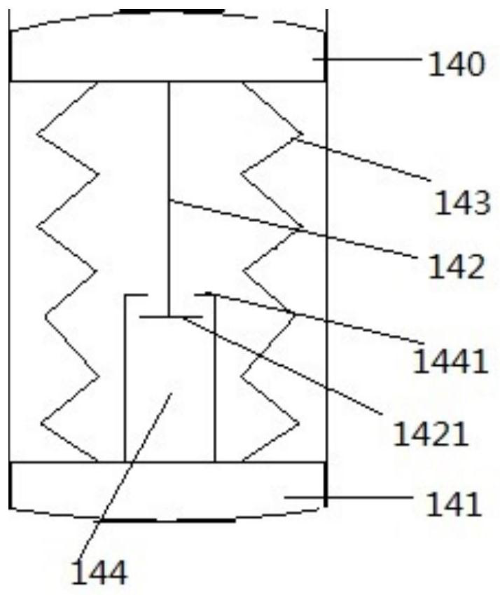
[0034] Embodiment 1 of the present invention provides an electrical connector applied in a vacuum chamber, wherein the vacuum chamber is provided with opposite first terminal posts and second terminal posts, and the electrical connector is arranged on the first terminal posts and the second terminal. figure 1 It shows a schematic structural diagram of an electrical connector used in a vacuum chamber according to Embodiment 1 of the present invention, please refer to figure 1 , the electrical connector includes:

[0035] The first conductive part 140 is arranged opposite to the first terminal, and can be in contact with or away from the first terminal;

[0036] The second conductive part 141 is in contact with the second terminal;

[0037] A stretchable conductive structure located between the first conductive part 140 and the second conductive part 141, the stretchable conductive structure 143, the first conductive part 140 and the second conductive part 141 form a sealed ca...

Embodiment 2

[0049] Embodiment 2 of the present invention provides an electrostatic chuck that can be placed in a vacuum chamber. figure 2 shows a schematic structural diagram of an electrostatic chuck according to Embodiment 2 of the present invention, please refer to figure 2 , the electrostatic chuck includes:

[0050] The metal base 110 , the ceramic body 100 disposed on the metal base 110 , the metal base 110 is provided with a longitudinally arranged accommodation cavity, and the electrical connector of the first embodiment is arranged in the accommodation cavity. The upper end of the accommodating cavity is a first terminal 101 for powering the ceramic body 100 , and the lower end of the accommodating cavity is a second terminal 111 for introducing external electrical signals.

[0051] In this embodiment, the second terminal post 111 is embedded in the metal base 110 and is insulated from the metal base 110 . The second terminal post 111 is used for electrical connection with ext...


PUM


Abstract

The invention discloses an electric connector applied to a vacuum chamber, an electrostatic chuck and semiconductor equipment. Specifically, a first binding post and a second binding post which are opposite to each other are arranged in the vacuum chamber, the electric connector is arranged between the first binding post and the second binding post, and the electric connector comprises: a first conductive part, which is disposed opposite to the first binding post, and can contact or be away from the first binding post; a second conductive part, which is in contact connection with the second binding post; a telescopic conductive structure, which is located between the first conductive part and the second conductive part, wherein the telescopic conductive structure, the first conductive part and the second conductive part form a sealed cavity; the telescopic conductive structure is used for being in a compressed state in an atmospheric environment, and the first conductive part is far away from the first binding post; the telescopic conductive structure can extend in a vacuum environment, and the first conductive part is in contact with the first binding post. According to the electric connector, in the atmospheric environment, the electric connector is in a compressed state, a circuit is disconnected, and in the vacuum environment, the electric connector can extend to achieve circuit connection.

Description

technical field [0001] The invention relates to the field of semiconductor equipment, and more particularly, relates to an electrical connector, an electrostatic chuck and a semiconductor equipment applied in a vacuum chamber. Background technique [0002] Plasma equipment is widely used in today's semiconductor, solar cell, flat panel display and other manufacturing processes. In the current plasma equipment, an electrostatic chuck (ESC for short) is usually used to replace the original mechanical chuck to clamp the wafer (wafer) during the process. Some electrostatic chucks are integral electrostatic chucks, and the other is split electrostatic chucks. [0003] The split electrostatic chuck is divided into two parts: the ceramic body of the electrostatic chuck and the metal base of the electrostatic chuck. The ceramic body of the electrostatic chuck is easy to disassemble and replace. Once part of it is damaged, it can be replaced with a new product. It does not need to b...

Claims


Application Information

Patent Timeline
Patent Type & Authority Applications(China)
IPC IPC(8): H01R13/02H01R13/24H01R24/00H01J37/32H01L21/683
CPCH01R13/02H01R13/24H01R24/005H01L21/6833H01J37/32715
Inventor 史全宇
Owner BEIJING NAURA MICROELECTRONICS EQUIP CO LTD
Learn More