Switching type loading adjustment device and method

A technology of adjusting device and loading rod, applied in measuring device, using stable tension/pressure test material strength, instrument and other directions, can solve the problems of low efficiency, can not meet the adjustment of loading uniformity, etc., to reduce the volume, The effect of improving loading efficiency and shortening lifting stroke

Pending Publication Date: 2021-04-30
INST OF MACHINERY MFG TECH CHINA ACAD OF ENG PHYSICS
View PDF0 Cites 1 Cited by
  • Summary
  • Abstract
  • Description
  • Claims
  • Application Information

AI Technical Summary

Problems solved by technology

[0004] The technical problem to be solved by the present invention is that when the existing two-bar loading device is used to load larger-sized products, it needs a long lifting distance, the efficiency is not high, and it requires the foundation to reserve a counterbore, which cannot meet the loading uniformity adjustment requirements
The purpose of the present invention is to provide a transfer-type loading adjustment device and method to solve the problem of realizing the small-stroke loading and loading uniformity adjustment functions of the two-bar loading device

Method used


Image

  • Switching type loading adjustment device and method
  • Switching type loading adjustment device and method
  • Switching type loading adjustment device and method

Examples


Embodiment 1

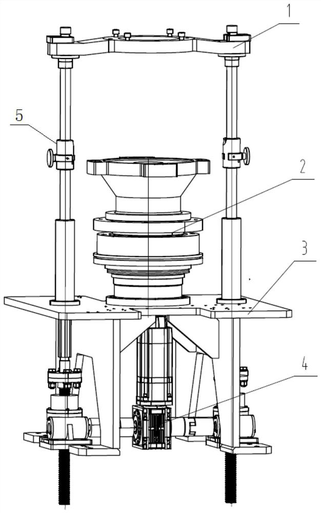
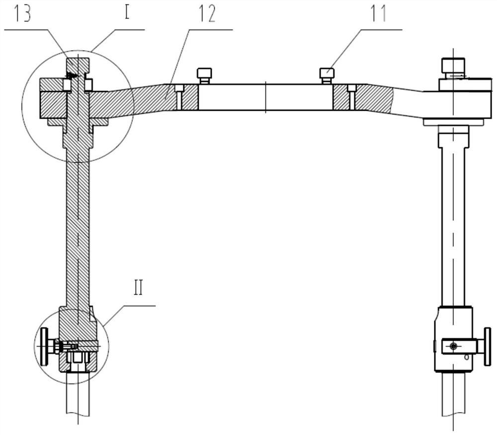
[0041] Such as Figure 1 to Figure 7 As shown, a transfer-type loading adjustment device of the present invention includes a mounting base 3, which provides an installation support interface; also includes a bearing platform 2, a synchronous lifting mechanism 4, and a loading mechanism 1, and the mounting base 3 is provided with Carrying platform 2, described carrying platform 2 is used for placing the product to be loaded and tested; The synchronous elevating mechanism 4 is provided under the described mounting base 3, and the screw rods on both sides of the synchronous lifting mechanism 4 pass upwardly through the mounting base 3 and the The loading mechanism 1 is connected; the loading mechanism 1 includes two loading rods 13 and a loading beam 12 , and the loading beam 12 is sheathed on the two loading rods 13 .

[0042] An adapter 5 is also included to realize the connection and locking of the screw rods on both sides of the synchronous lifting mechanism 4 and the loading...

Embodiment 2

[0045] Such as Figure 1 to Figure 7 As shown, the difference between this embodiment and Embodiment 1 is that the adapter 5 includes a limit ring 17, a locking screw 18, and a wedge post 19, and the wedge post 19 is installed in the end of the loading rod 13. The locking screw 18 is inserted into the wedge column 19 from the side of the loading rod 12; the limit ring 17 is installed on the side of the loading rod 13 and embedded in the locking screw 18 slot to limit the lateral movement of the locking screw 18 , thereby tightening the wedge column 19 to eliminate backlash.

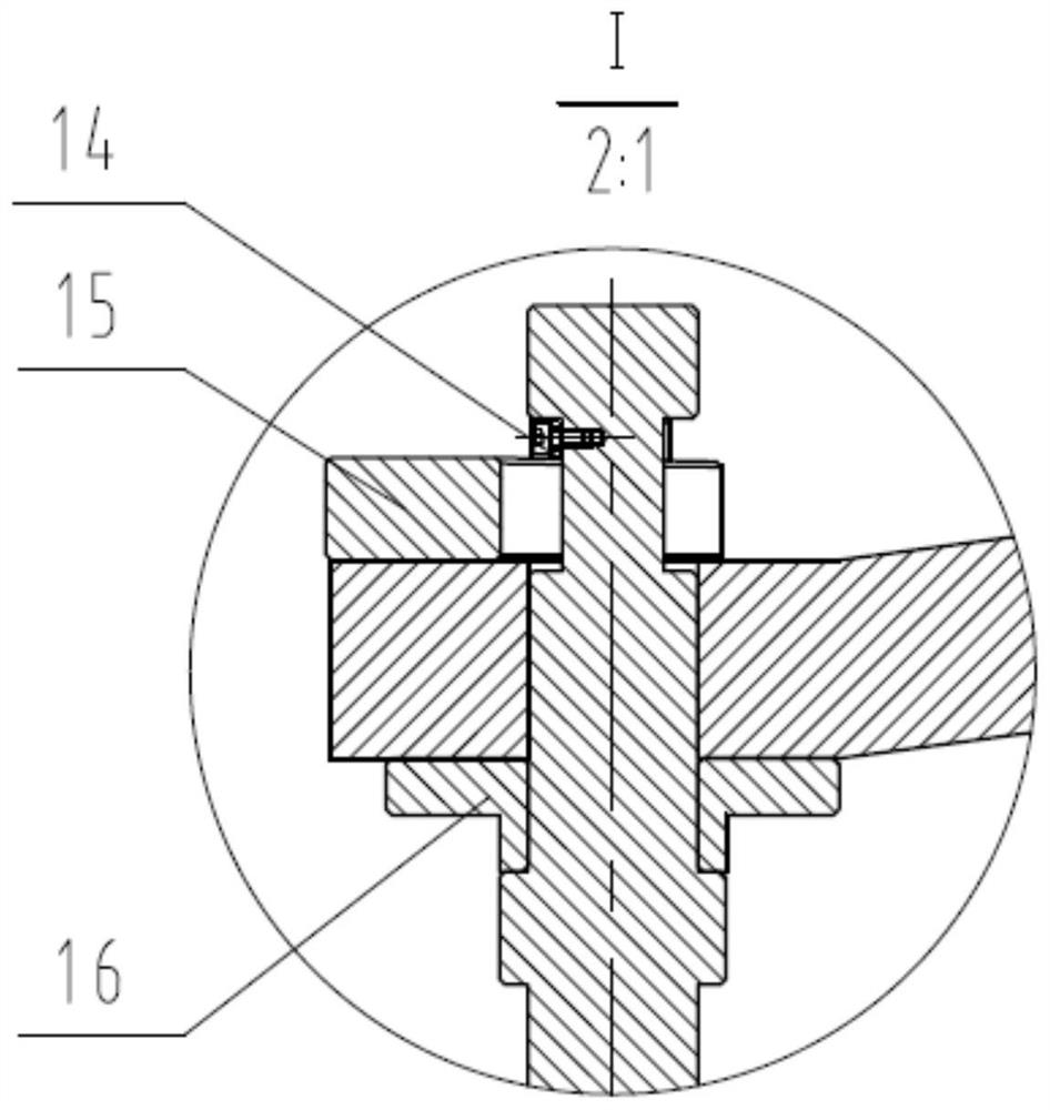
[0046]In this embodiment, the loading mechanism 1 further includes a slanted ring 14, a wedge 15, and a sleeve 16, and the loading beam 12 is sleeved on the two loading rods 13 through the sleeve 16; The block 15 and the slant ring 14 are locked; the slant ring 14 is mounted on the journal of the loading rod 13 by screws.

[0047] In this embodiment, the loading mechanism 1 further includes adjustment p...

Embodiment 3

[0056] Such as Figure 1 to Figure 7 As shown, the difference between this embodiment and Embodiment 2 is that the adjusting member can also be realized by adjusting bolts or adjusting studs, and the number and arrangement form are not limited.

[0057] In this embodiment, the synchronous lifting mechanism 4 is realized by using a synchronous motor, a synchronous electric cylinder, a hydraulic cylinder or an air cylinder.


PUM


Abstract

The invention discloses a switching type loading adjustment device and method, and the device comprises a mounting base which provides a mounting support interface; the device further comprises a bearing table, a synchronous lifting mechanism and a loading mechanism, wherein the bearing table is arranged on the mounting base, and the bearing table is used for placing a to-be-detected product. The synchronous lifting mechanism is arranged below the mounting base, and screw rods on the two sides of the synchronous lifting mechanism upwards penetrate through the mounting seat and are connected with a loading mechanism; the loading mechanism comprises two loading rods and a loading beam, and the loading beam is arranged on the two loading rods in a sleeving manner. The device further comprises an adapter, and the connecting and locking of the screw rods on the two sides of the synchronous lifting mechanism and the loading rod are realized. The device is simple and reasonable in structure, rapid installation of the loading rod and the loading beam is achieved, and repeated positioning is reliable; the size of the loading device is reduced, the lifting stroke is shortened, and the loading efficiency is improved; and a loading gap uniformity adjusting function is also realized.

Description

technical field [0001] The invention relates to the technical field of loading devices, in particular to a transfer-type loading adjustment device and method. Background technique [0002] The two-bar loading device is a common lifting device. It needs a long lifting distance when loading large-sized products. The efficiency is not high, it takes up a lot of space, and requires the foundation to reserve a counterbore, and generally does not have a loading gap. Or force uniformity adjustment function. It cannot meet the requirements of efficient loading and uniformity adjustment in a compact space during product assembly. [0003] Therefore, it is necessary to design a loading device with small stroke and adjustable loading uniformity. Contents of the invention [0004] The technical problem to be solved by the present invention is that when the existing two-bar loading device is used to load larger-sized products, it needs a long lifting distance, the efficiency is not h...

Claims


Application Information

Patent Timeline
IPC IPC(8): G01N3/02G01N3/04G01N3/12
CPCG01N3/02G01N3/04G01N3/12
Inventor 刘延龙唐恺殷俊张连新陈华贾玉辉
Owner INST OF MACHINERY MFG TECH CHINA ACAD OF ENG PHYSICS
Why Eureka
Try Eureka