An Automatic Lifting Roller Bed for Body Welding

An automatic lifting and body technology, applied in welding equipment, auxiliary welding equipment, welding/cutting auxiliary equipment, etc., can solve the problems of reduced work efficiency, long lifting time, difficult welding process, etc., and achieves convenient operation, simple structure, Ease of maintenance

Active Publication Date: 2018-09-04
SHANGHAI FULANGDE MACHINERY EQUIP
View PDF7 Cites 0 Cited by
  • Summary
  • Abstract
  • Description
  • Claims
  • Application Information

AI Technical Summary

Problems solved by technology

[0002] In the automobile assembly line, there are many welding processes for the body, and the heavy body is inconvenient to lift, adjust and move, and the welding process is difficult to complete
The lifting of the existing lifting roller bed is generally a linear motion driven by hydraulic devices, motors and other driving equipment, which has high requirements for the driving equipment, and for occasions that only need a small lifting, there are disadvantages of complex structure and long lifting time , which reduces the work efficiency, and it is difficult for this kind of drive equipment to satisfy the alignment accuracy of the lifting process

Method used


Image

  • An Automatic Lifting Roller Bed for Body Welding

Examples


Embodiment 1

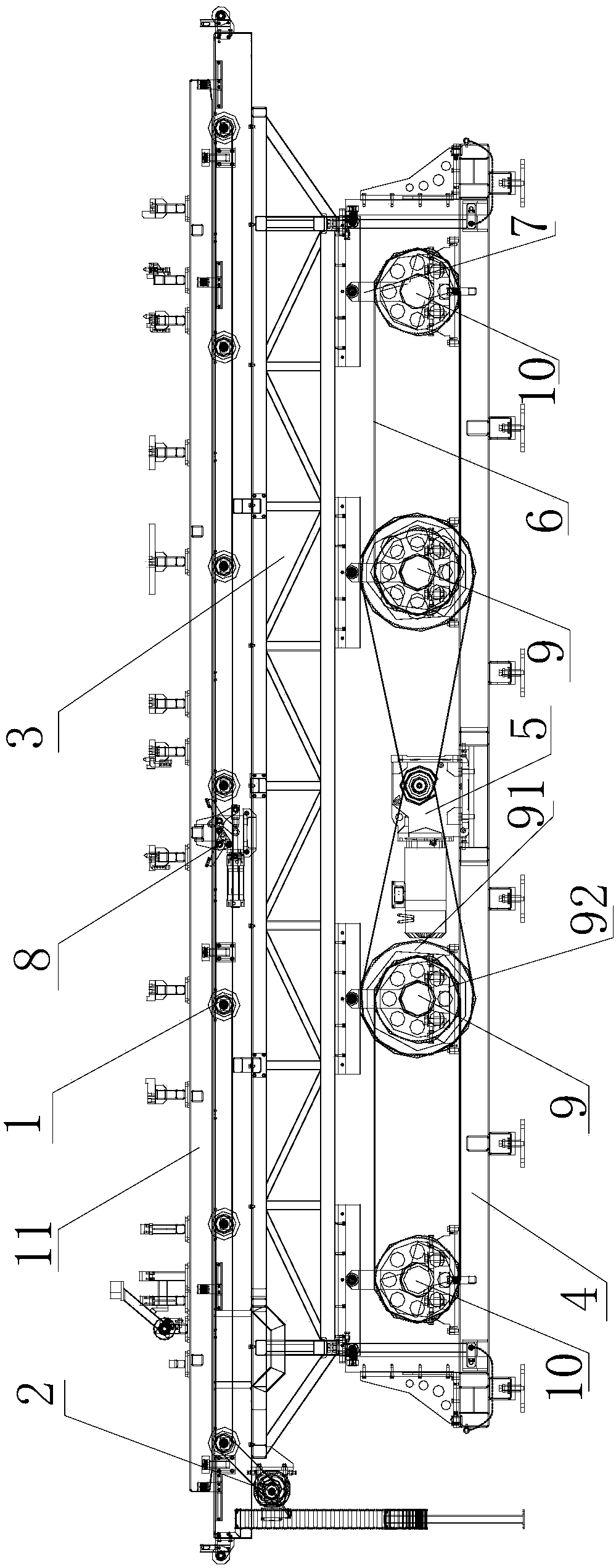
[0022] An automatic lifting roller bed for body welding, such as figure 1 As shown, it includes a roller table 1, a roller table driving mechanism 2, a welding frame 3, a bottom bracket 4 and a lifting mechanism. The roller table 1 is driven by the roller table driving mechanism 2 and is fixed on the welding frame 3. The roller table driving mechanism 2 is composed of The roller table driving motor, pulley and belt are composed, and the roller table driving motor is fixed on the welding frame. The bottom bracket 4 is provided with vertical slide rails, and the welding frame 3 is provided with sliders or guide wheels matching the slide rails, and the welding frame 3 and the bottom bracket 4 slide vertically through the sliders or guide wheels and the slide rails Connection, the slide rail is provided with a lifting limit block. The lifting mechanism is arranged between the welding frame 3 and the bottom bracket 4. The lifting mechanism includes a motor assembly 5 composed of a...

Embodiment 2

[0025] The automatic lifting roller bed used for body welding of this embodiment is basically the same as that of Embodiment 1, the difference is that the big wheel 91 of the first synchronous pulley 9 of this embodiment is fixed on the rotating shaft of the first synchronous pulley 9 On the top, the small wheel 92 is rotatably sleeved on the rotating shaft of the first synchronous pulley 9, and a clutch mechanism is provided between the large wheel 91 and the small wheel 92, and the rocker arms 7 on the two first synchronous pulleys 9 The length is the same, the length of the rocking arm 7 on the two second synchronous pulleys 10 is the same, and the length of the rocking arm 7 on the first synchronous pulley 9 is greater than the length of the rocking arm 7 on the second synchronous pulley 10 . Wherein, the clutch mechanism includes a latch, a cylinder for driving the latch to reciprocate, and latch holes respectively arranged on the big wheel 91 and the small wheel 92 .

[...

Embodiment 3

[0028] This embodiment is basically the same as Embodiment 1, except that each synchronous pulley of this embodiment is provided with a hole for weight reduction.


PUM


Abstract

The invention relates to an automatic lifting roller bed for welding vehicle bodies. The automatic lifting roller bed comprises a roller way (1), a roller way driving mechanism (2), a welding framework (3), a bottom support (4) and a lifting mechanism, wherein the roller way (1) is driven by the roller way driving mechanism (2) and is fixed on the welding framework (3); the welding framework (3) and the bottom support (4) are in sliding connection with each other in a vertical direction; the lifting mechanism is arranged between the welding framework (3) and the bottom support (4) and comprises a motor assembly (5) and at least one synchronous belt wheel and a synchronous belt (6); a rocker arm (7) is arranged on each synchronous belt wheel; one end of the rocker arm (7) is coaxial with the synchronous belt wheel, and a rolling wheel is arranged at the tail of the other end of the rocker arm (7); rolling wheel sliding grooves matched with the rolling wheels are formed in the bottom of the welding framework (3). Compared with the prior art, the automatic lifting roller bed for welding vehicle bodies is especially applicable to places with small lifting ranges; a clutch mechanism is arranged, so that the roller bed also has two lifting strokes and is applicable to more operating conditions.

Description

technical field [0001] The invention belongs to the field of automatic assembly of automobiles, and relates to a fixing and circulation device for welding parts in an automobile assembly production line, in particular to an automatic lifting roller bed for body welding. Background technique [0002] In the automobile assembly line, there are many welding processes for the body, and the heavy body is inconvenient to lift, adjust and move, and the welding process is difficult to complete. The lifting of the existing lifting roller bed is generally a linear motion driven by hydraulic devices, motors and other driving equipment, which has high requirements for the driving equipment, and for occasions that only need a small lifting, there are disadvantages of complex structure and long lifting time , reducing work efficiency, and it is difficult for this kind of drive equipment to satisfy the alignment accuracy of the lifting process. Contents of the invention [0003] The obj...

Claims


Application Information

Patent Timeline
Patent Type & Authority Patents(China)
IPC IPC(8): B23K37/047
CPCB23K37/047B23K2101/006
Inventor 刘庆刚程飞宋旭东
Owner SHANGHAI FULANGDE MACHINERY EQUIP
Why Eureka
Try Eureka