
Exhaust valve structure of low-speed two-stroke marine diesel engine

A marine diesel engine and exhaust valve technology, which is applied to mechanical equipment, combustion engines, engine components, etc., can solve the problems of exhaust gas accumulation and inability to discharge, and achieve the effects of low exhaust gas flow resistance, easy processing, and improved scavenging efficiency

Active Publication Date: 2022-06-07
TIANJIN UNIV
View PDF0 Cites 0 Cited by
  • Summary
  • Abstract
  • Description
  • Claims
  • Application Information

AI Technical Summary

Problems solved by technology

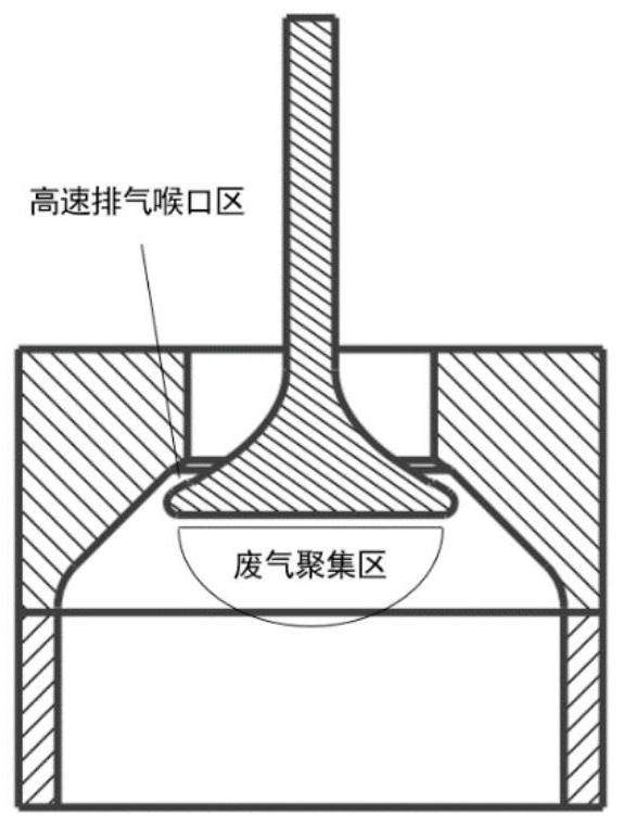
[0004] The purpose of the present invention is to provide a low-speed two-stroke marine diesel engine exhaust valve structure, which can solve the problem that the exhaust gas under the valve disc cannot be discharged due to the accumulation of exhaust gas during the exhaust process, so as to improve the scavenging efficiency

Method used


Image

  • Exhaust valve structure of low-speed two-stroke marine diesel engine
  • Exhaust valve structure of low-speed two-stroke marine diesel engine
  • Exhaust valve structure of low-speed two-stroke marine diesel engine

Examples


Embodiment 1

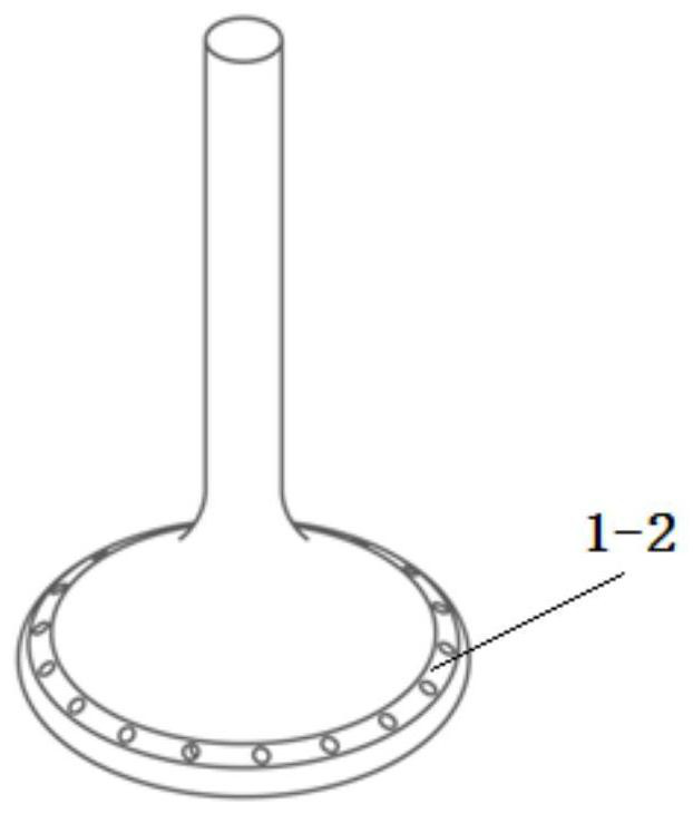
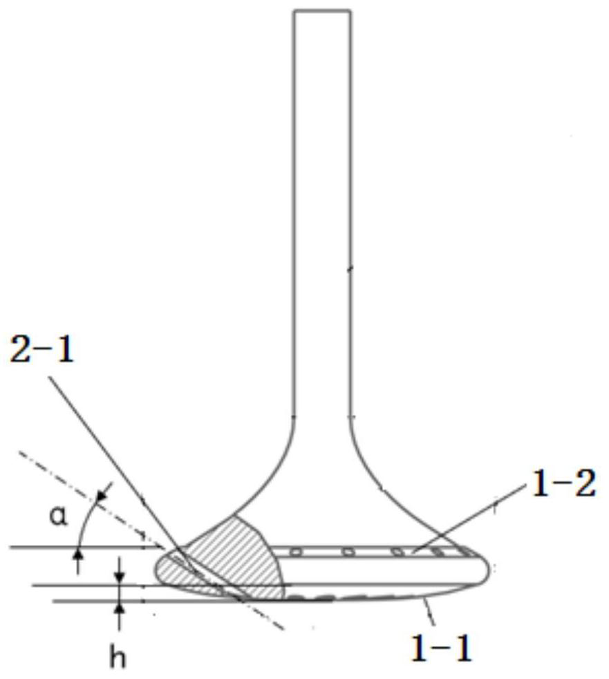
[0025] The exhaust gas runners are evenly arranged in a single ring around the center line of the exhaust valve, and the height h of the arc surface of the exhaust valve bottom surface from the horizontal line is 15mm (eg image 3 , Figure 4 ); the number of exhaust runners is 18. The angle α between the axis of the exhaust gas flow channel and the horizontal plane is 40°. The angle β between the centerline of the exhaust gas runner and the centerline of the valve projected to the horizontal plane is 15° (such as Figure 4 ); the section of the exhaust gas flow channel is circular and the diameter is 10mm. The chamfer of the exhaust gas runner intake port at the bottom surface of the valve is 2mm×2mm.

[0026] The experimental results show that the exhaust gas in the exhaust gas accumulation area under the exhaust valve is reduced by about 50% from the opening to the closing of the exhaust valve of the present invention, and the scavenging efficiency is improved by about 2...

Embodiment 2

[0028] The exhaust gas runner is evenly arranged around the center line of the exhaust valve with double rings in the circumferential direction, and the height h of the arc surface of the exhaust valve bottom surface from the horizontal line is 15mm (such as Figure 5 , Image 6 ); the number of exhaust gas flow channels is 18, of which the number of exhaust gas flow channels in the inner and outer rings is 9. The angle α between the axis of the exhaust gas flow channel of the inner ring and the horizontal plane is 30°; the angle α' between the axis of the exhaust gas flow channel of the outer ring and the horizontal plane is 40°. The angle β between the centerline of the exhaust gas runner and the centerline of the valve projected to the horizontal plane is 15° (such as Figure 4 ); the section of the exhaust gas flow channel is circular and the diameter is 10mm. The chamfer of the exhaust gas runner intake port at the bottom surface of the valve is 2mm×2mm.

[0029] The e...


PUM


Abstract

The invention discloses an exhaust valve structure for a low-speed two-stroke marine diesel engine. The scheme is as follows: the exhaust valve is provided with an exhaust flow passage, and the inlet of the exhaust passage is arranged on the bottom surface of the exhaust valve; the outlet is arranged on the sealing surface of the exhaust valve. The exhaust runners are arranged circumferentially along the central axis of the exhaust valve. The flow channel can choose a single-ring or double-ring structure, and the angle α between the centerline of the single-ring exhaust flow channel and the horizontal plane is 20° to 40°. The double-ring layout structure is divided into inner ring and outer ring, the inner ring flow path angle α is 20°-40°; the outer ring flow path angle α' is 30°-50°. The angle β between the centerlines of all exhaust runners and the centerline of the exhaust valve projected onto the horizontal plane is 10°-20°. By setting the exhaust flow channel between the bottom surface of the valve and the sealing surface, the residual exhaust gas accumulated in the exhaust gas accumulation area under the valve is effectively eliminated, and the scavenging efficiency can be obviously improved. Through the design of different structural angles of the exhaust flow channel, the flow resistance of the exhaust gas is minimized, and the working performance of the diesel engine is improved.

Description

technical field [0001] The invention belongs to an engine structure, in particular to an exhaust valve structure of a low-speed two-stroke marine diesel engine. Background technique [0002] The scavenging process of the marine low-speed two-stroke diesel engine covers the entire stage from the opening of the scavenging port (the end of the power stroke) to the closing of the exhaust valve (the end of the compression stroke), including providing fresh charge, discharging the exhaust gas in the cylinder, and providing an initial vortex to promote mixing. The efficient scavenging process can effectively improve the combustion performance of marine low-speed two-stroke diesel engines, thereby achieving the goals of increasing power, reducing fuel consumption and emissions, and enhancing engine reliability. [0003] To improve the scavenging performance and scavenging efficiency of marine diesel engines, the main research is on the structure of scavenging ports, such as the opti...

Claims


Application Information

Patent Timeline
Patent Type & Authority Patents(China)
IPC IPC(8): F01L3/06F01L3/20
CPCF01L3/06F01L3/20Y02T10/12
Inventor 鲁祯高玉川王天友刘梦雨卢天龙
Owner TIANJIN UNIV
Learn More