
Convenient-to-disassemble supporting frame base with angle conversion function for assembly building

A technology for angle conversion and supporting frames, which is applied in buildings, building components, building structures, etc. It can solve problems such as troublesome disassembly, time-consuming and labor-intensive operations, and inability to achieve fixing effects.

Inactive Publication Date: 2021-04-30
温州艾米华农业科技有限公司
View PDF0 Cites 5 Cited by
  • Summary
  • Abstract
  • Description
  • Claims
  • Application Information

AI Technical Summary

Problems solved by technology

[0004] The purpose of the present invention is: in order to solve the general need to use the support frame in the building assembly process, and the support frame generally needs to be installed on the base, to achieve a good support effect, so that the support frame can be installed conveniently, but the existing The base is generally fixed to the supporting frame by bolts or welding. When any component of the base and the supporting frame is damaged, the two need to be disassembled and matched with intact components for use. However, it is very troublesome to disassemble, and welding and bolts The way of connection cannot achieve a good fixing effect. At the same time, in the prior art, when adjusting the angle of the supporting frame, it is necessary to control the movement and adjustment of the entire base. The operation is time-consuming and laborious, and there is a certain inconvenience. Detachable support frame base for construction

Method used


Image

  • Convenient-to-disassemble supporting frame base with angle conversion function for assembly building
  • Convenient-to-disassemble supporting frame base with angle conversion function for assembly building
  • Convenient-to-disassemble supporting frame base with angle conversion function for assembly building

Examples


Embodiment Construction

[0033] The following will clearly and completely describe the technical solutions in the embodiments of the present invention with reference to the accompanying drawings in the embodiments of the present invention. Obviously, the described embodiments are only some, not all, embodiments of the present invention. Based on the embodiments of the present invention, all other embodiments obtained by persons of ordinary skill in the art without creative efforts fall within the protection scope of the present invention.

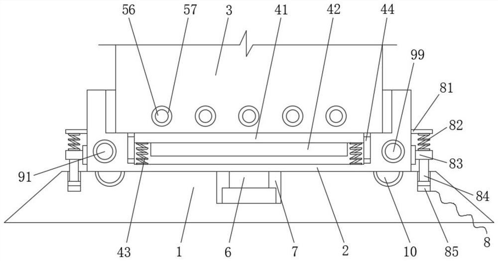
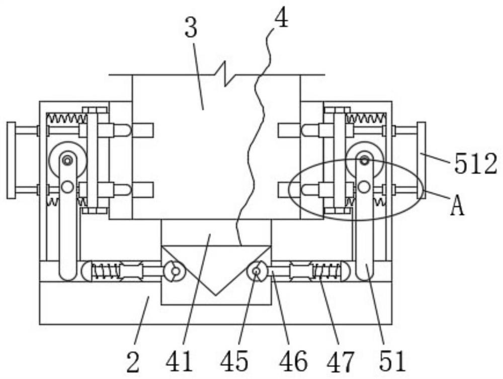
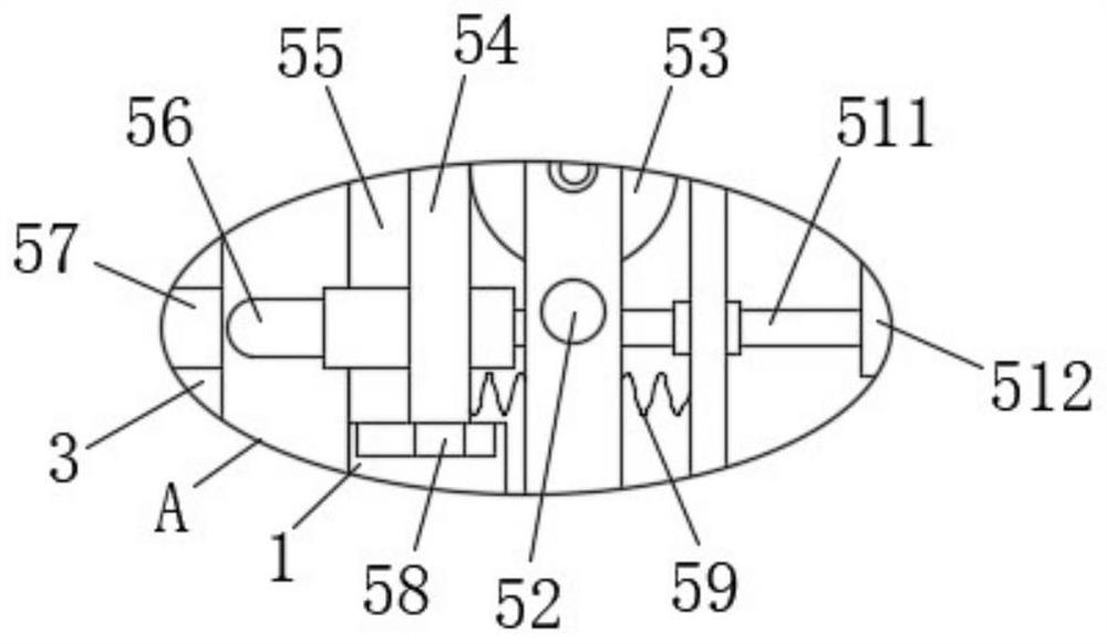
[0034] see Figure 1-6 , the present invention provides a technical solution: a detachable support frame base for assembly building with angle conversion function, including a base 1 and a support plate 2, the upper surface of the base 1 is attached with a support plate 2, and the support plate 2 The upper surface is provided with a storage tank, the storage tank is provided with a frame 3, the lower surface of the storage tank inner wall is provided with an empty sl...


PUM


Abstract

The invention discloses a convenient-to-disassemble supporting frame base with an angle conversion function for an assembly building, and belongs to the technical field of building assembly. The convenient-to-disassemble supporting frame base comprises a base body and a supporting plate, wherein the supporting plate is attached to the upper surface of the base body, a storage groove is formed in the upper surface of the supporting plate, a frame is arranged in the storage groove, an empty groove is formed in the lower surface of the inner wall of the storage groove, and a positioning mechanism is arranged in the empty groove. According to the convenient-to-disassemble supporting frame base, the positioning mechanism is arranged, when the frame is placed in the storage groove, a fixing plate enters the groove, at the moment, a triangular block can extrude two rollers, the two rollers drive two arc-shaped blocks to be far away from each other through two first sliding rods respectively, a baffle can rotate under the action of a pin shaft when being extruded by the arc-shaped blocks, at the moment, the baffle drives an extrusion roller to move to extrude a push plate, the push plate drives a sleeve to move, so that an inserting block can move and be inserted into an inserting groove, and at the moment, the frame can be effectively fixed.

Description

technical field [0001] The invention belongs to the technical field of building assembly, and in particular relates to a detachable supporting frame base for assembling buildings with the function of angle conversion. Background technique [0002] Construction refers to the assets made by man-made construction, which belongs to the category of fixed assets, including two categories: houses and structures. Housing refers to engineering buildings for people to live, work, study, produce, operate, entertain, store items and carry out other social activities. What is different from buildings are structures, which refer to engineering buildings other than houses, such as walls, roads, dams, wells, tunnels, water towers, bridges, and chimneys. [0003] In the process of building assembly, a support frame is generally required, and the support frame generally needs to be installed on the base to achieve a good support effect, so that the support frame can be easily installed, but ...

Claims


Application Information

Patent Timeline
Patent Type & Authority Applications(China)
IPC IPC(8): E04B1/00E04B1/343E04B1/344
CPCE04B1/0007E04B1/34315E04B1/34352E04B1/3448
Inventor 马丽艳
Owner 温州艾米华农业科技有限公司
Learn More