Aircraft Controlled by Pneumatic Vortex Generator and Plasma Synthetic Jet

A technology of vortex generator and synthetic jet, which is applied in the direction of space navigation aircraft, aircraft, motor vehicles, etc., can solve problems such as inability to adjust according to the flight state, the influence of engine thrust and stable working boundary, and blade shedding, and achieve great application potential. , Good control effect, reducing the effect of total pressure distortion

Active Publication Date: 2022-04-15
NANJING UNIV OF AERONAUTICS & ASTRONAUTICS
View PDF9 Cites 0 Cited by
  • Summary
  • Abstract
  • Description
  • Claims
  • Application Information

AI Technical Summary

Problems solved by technology

There has been a lot of research work at home and abroad to realize the effective control of the internal swirl flow and its induced separation in the buried inlet. Among them, the active control method mainly uses the jet vortex generator, but the jet vortex generator alone requires In order to achieve a better control effect, it is often necessary to divert the airflow exceeding 1% of the mainstream flow from the high-pressure compressor, which has a great impact on the thrust and stable working boundary of the engine, while the passive flow control method is mainly aerodynamic vortex generation The protruding blades not only have the risk of falling off but also cannot be adjusted according to the flight state. Therefore, it is necessary to develop a flow control method that consumes less energy and can actively adapt to the state of the aircraft.

Method used


Image

  • Aircraft Controlled by Pneumatic Vortex Generator and Plasma Synthetic Jet
  • Aircraft Controlled by Pneumatic Vortex Generator and Plasma Synthetic Jet
  • Aircraft Controlled by Pneumatic Vortex Generator and Plasma Synthetic Jet

Examples


Embodiment Construction

[0026] The present invention will be described in further detail below in conjunction with the accompanying drawings and specific embodiments.

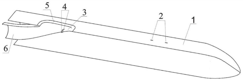
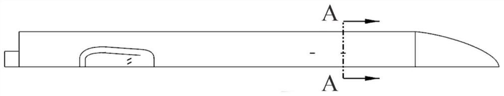
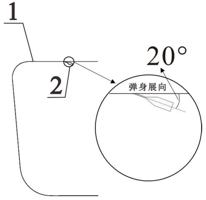
[0027] refer to Figure 1 to Figure 4 As shown, the aircraft controlled by the combination of the pneumatic vortex generator and the plasma synthetic jet provided by the present invention includes a projectile body 1, a pneumatic vortex generator 2 positioned on the projectile body 1, and an embedded air intake positioned in the projectile body. Road 6, the plasma synthetic jet actuator 4 located in the buried air inlet 6. The designed cruise Mach number of the embedded air inlet 6 in the aircraft is 0.7, and the exit Mach number is 0.5. The pneumatic vortex generator 2 has two pairs, and the pneumatic vortex generator 2 is located on the projectile surface upstream of the entrance of the embedded air inlet 6, and the plasma synthetic jet exciter 4 has two pairs, and is located at the embedded The air inlet guide surface 3 of the ai...


PUM


Abstract

The invention discloses an aircraft controlled by a combination of a pneumatic vortex generator and a plasma synthetic jet, which comprises a projectile body, an embedded air inlet, a pneumatic vortex generator located on the projectile body, and a jet on the guide surface of the air inlet. Plasma synthetic jet actuator. Among them, part of the incoming boundary layer is blown off by a pneumatic vortex generator, so that the entrainment vortex sucks the fluid with higher energy. A new vortex is induced to force the high-energy flow at the bottom to flow to the center of the pipe while keeping the vortex intensity small, thereby further reducing the total pressure distortion of the outlet section of the inlet. The invention makes full use of the advantages of the two control methods, the control effect is better than that of the single control, the air consumption is less than 0.5% of the engine flow, and the flow control state can be adaptively adjusted according to the flight state, which has broad engineering and practical prospects.

Description

technical field [0001] The invention relates to the field of aircraft design, in particular to a buried air intake. Background technique [0002] The air intake is one of the important aerodynamic components of the air-breathing propulsion system. The design of the advanced air intake must pay attention to its electromagnetic stealth, structural length and weight, external resistance, and integration with the aircraft while tapping its own aerodynamic potential. And other integration factors, embedded air intake came into being. [0003] The buried air intake has a unique integration advantage because it does not present any protruding parts on the fuselage: first, the inlet is completely integrated with the surface of the fuselage, so it can significantly reduce the windward resistance of the aircraft and greatly reduce the air intake. Secondly, it effectively reduces the electromagnetic echo in the inlet cavity and the corner area between the outer surface of the inlet an...

Claims


Application Information

Patent Timeline
Patent Type & Authority Patents(China)
IPC IPC(8): B64C23/06B64D33/02B64G1/10B64G1/66
CPCB64C23/06B64D33/02B64G1/10B64G1/66Y02T50/10
Inventor 黄河峡于航罗中岐秦源谭慧俊林正康蔡佳
Owner NANJING UNIV OF AERONAUTICS & ASTRONAUTICS
Why Eureka
Try Eureka