Mobile reverse alignment vehicle wireless charging system and public parking area thereof

A technology for wireless charging and parking areas, applied in electric vehicle charging technology, charging stations, motor vehicles, etc., can solve the problems of slow alignment process, cumbersome cable laying projects, and high technical requirements for drivers to park, so as to improve efficiency and improve efficiency. Accuracy, Improved Efficiency and User Experience, Effectiveness of Improved Efficiency and Experience

Pending Publication Date: 2021-04-30
宫雪峰
View PDF0 Cites 1 Cited by
  • Summary
  • Abstract
  • Description
  • Claims
  • Application Information

AI Technical Summary

Problems solved by technology

[0008] 1. When an electric vehicle is charged in a public wireless charging area (such as a public parking lot with wireless charging equipment installed), it is necessary to align the wireless charging receiving coil at the bottom of the vehicle with the wireless charging transmitting coil fixed on the ground to ensure charging efficiency The existing alignment method is generally that the driver controls the electric vehicle to locate and align the wireless charging transmitting coil according to the set positioning marks, which requires the driver's manual control to realize the alignment between the wireless charging transmitting coil and the wireless charging receiving coil. Alignment, this alignment process is slow, requires high parking skills of the driver, and is inefficient
[0009] 2. The realization of wireless charging requires the use of cables connected to the power grid to provide continuous power for the wireless charging transmitting coil, and the cable laying project is relatively cumbersome

Method used


Image

  • Mobile reverse alignment vehicle wireless charging system and public parking area thereof
  • Mobile reverse alignment vehicle wireless charging system and public parking area thereof
  • Mobile reverse alignment vehicle wireless charging system and public parking area thereof

Examples


Embodiment 1

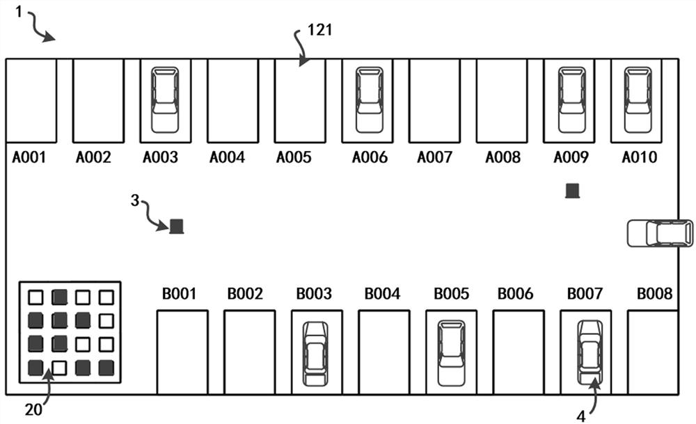
[0077] refer to Figure 1~6 , Figure 10 as well as Figure 11 ; This embodiment provides a mobile reverse alignment vehicle wireless charging system, including a wireless charging area 20 set in a public parking area 1, a plurality of AGV3, a plurality of vehicles 4 with a wireless charging protocol, and the AGV3 establishes the dispatch server 5 of wireless communication.

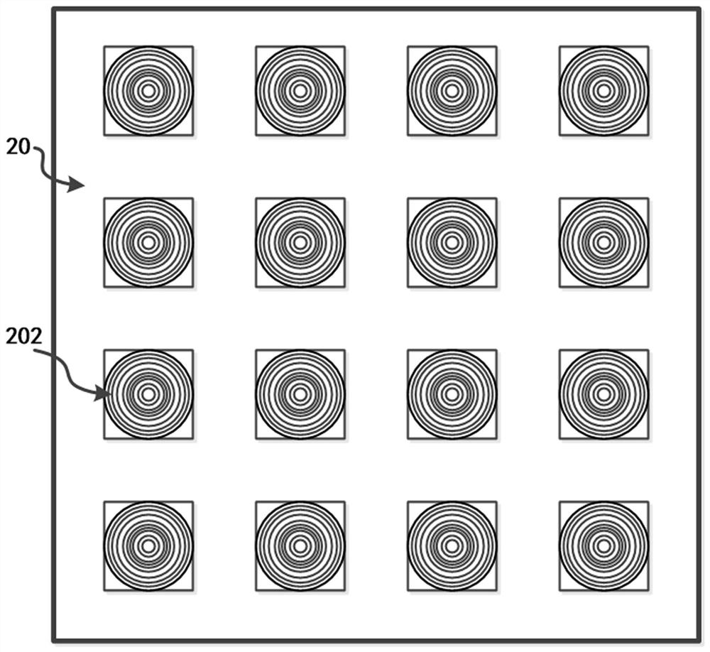
[0078] The public parking area 1 mentioned in this embodiment can be understood as a public parking lot integrated with vehicle wireless charging facilities; the wireless charging area 20 set in the public parking area 1 provides power for a plurality of AGV3, referred to herein The provision of electric power is not understood in a narrow sense to provide the power source required for driving the AGV3, but to use the AGV3 as a power transfer mechanism, and the power is provided to the vehicle 4 that needs to be charged by means of wireless transmission through the AGV3; Of course, the power required f...

Embodiment 2

[0117] refer to Figure 12 As shown; the difference between this embodiment and Embodiment 1 is that this embodiment provides another way to align the second transmitting coil 305 with the second receiving coil 401, specifically: the vehicle 4 also Including: a mark arranged under the vehicle 4 and corresponding to the alignment point of the second receiving coil 401 up and down; the AGV3 also includes: connected to the charging control unit 306 and used to obtain image data above the AGV3 The camera 308; the charging control unit 306 is also used to: determine the position of the marker according to the image data acquired by the camera 308; and control the second launch of the AGV3 according to the position of the marker The coil 305 is aligned with the second receiving coil 401 of the vehicle 4 .

[0118] Wherein, the mark is set on the chassis, which can be a special shape or pattern; the camera 308 is set on the top surface of the AGV3, and it transmits the captured imag...

Embodiment 3

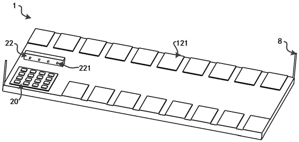
[0121] refer to figure 2 as well as Figure 13 As shown; this embodiment is an extension on the basis of Embodiment 1, specifically, the wireless charging system provided by this embodiment also includes a wired charging area 22 arranged in the public parking area 1, and the wired charging area 22 A plurality of fixed charging males 221 connected to the grid 6 are provided; the AGV3 also includes a third charging receiving circuit 309 connected to the first storage battery 303 and a charging bus connected to the third charging receiving circuit 309 Head 310; the charging female head 310 is at the same height as the charging male head 221 relative to the ground.

[0122] Wherein, the height of the charging female head 310 and the charging male head 221 relative to the ground is the same, which means that when the charging female head 310 and the charging male head 221 are horizontally docked, the height makes the charging male head 221 just snap into the charging female head 31...


PUM


Abstract

The invention discloses a mobile reverse alignment vehicle wireless charging system and a public parking area thereof. The system comprises a wireless charging area, an AGV, a vehicle and a scheduling server; the wireless charging area comprises a first charging transmitting circuit and first transmitting coils; the AGV comprises a first receiving coil, a first charging receiving circuit, a first battery, a second charging transmitting circuit, and a second transmitting coil; the vehicle comprises a second receiving coil, a second charging receiving circuit, and a second battery; the scheduling server is used for sending an electric quantity supplementing instruction to the AGV, and sending a wireless charging instruction for the vehicle corresponding to the parking space information to one AGV; the AGV further comprises a charging control unit used for driving the AGV to move to the position above one of the first transmitting coils so as to supplement electric quantity to the first storage battery, and driving the AGV to move to the position below the vehicle corresponding to the parking space information so as to carry out wireless charging on the second storage battery, and then the wireless charging efficiency and experience of the vehicle are improved.

Description

technical field [0001] The invention relates to the technical field of vehicle wireless charging, in particular to a mobile reverse alignment vehicle wireless charging system and a public parking area thereof. Background technique [0002] Car wireless charging technology is to charge electric vehicles through non-contact power transmission methods such as electromagnetic induction, electromagnetic resonance, and radio frequency without connecting through physical wires. [0003] There are three main ways to charge electric vehicles: [0004] 1. Electromagnetic induction type: It is a widely used and developed form of wireless charging for automobiles. Its principle is to use the principle of electromagnetic induction. There is a coil at the sending end and receiving end, and a certain frequency of alternating current is passed through the primary coil. Electromagnetic induction generates a certain current in the secondary coil, which transfers energy from the transmitting ...

Claims


Application Information

Patent Timeline
Patent Type & Authority Applications(China)
IPC IPC(8): B60L53/38B62D63/02H02J50/12H02J50/90
CPCB62D63/025B60L53/38H02J50/12H02J50/90Y02T10/70Y02T10/7072Y02T90/12Y02T90/16Y02T90/167Y04S30/12
Inventor 宫雪峰
Owner 宫雪峰
Why Eureka
Try Eureka