An aggregate processing and screening device for building construction
A screening device and aggregate technology, which is applied in the direction of separating solids from solids with airflow, filtering, solid separation, etc., can solve the inconvenience of moving large production lines, low aggregate efficiency, and incomplete aggregate screening and other problems, to achieve the effect of small space occupation, convenient processing and convenient movement
- Summary
- Abstract
- Description
- Claims
- Application Information
AI Technical Summary
Problems solved by technology
Method used
Image
Examples
Embodiment 1
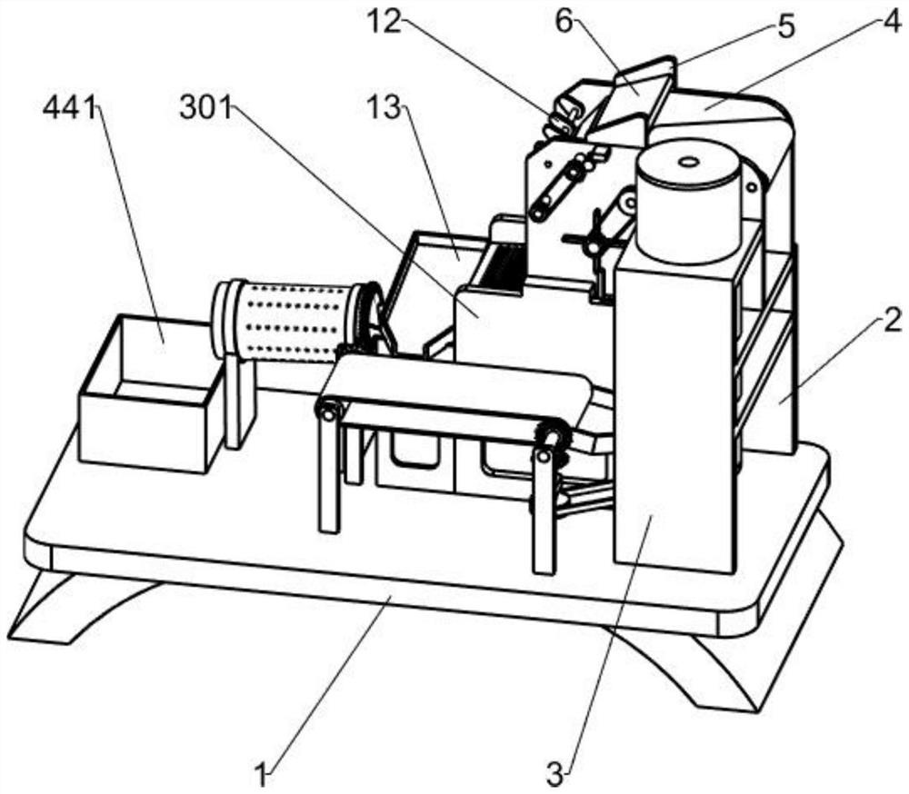
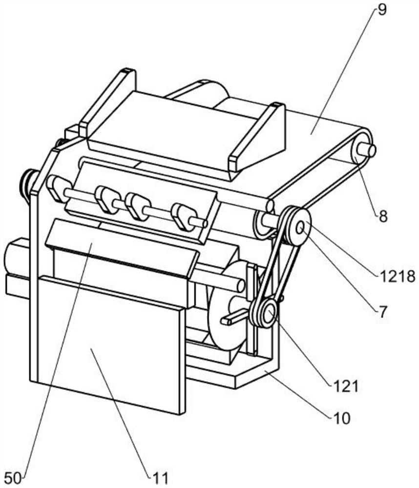
[0033] Such as Figure 1-2 As shown, an aggregate processing and screening device for building construction includes a base frame 1, a first mounting frame 2, a first fixing frame 3, a second mounting frame 301, a mounting plate 4, a first connecting plate 5, a A baffle plate 6, a first rotating shaft 7, a conveying roller 8, a conveyor belt 9, a material retaining frame 10, a second baffle plate 11, a crushing mechanism 12 and a screening mechanism 13, and the right side of the bottom frame 1 top is connected with a first mounting frame 2. The first mounting frame 3 is installed on the top of the bottom frame 1 on the front side of the first mounting frame 2, and the second mounting frame 301 is installed on the lower part of the left side wall of the first mounting frame 3. The first mounting frame 2 and the second mounting frame The upper part of the inner side wall of 301 is provided with a mounting plate 4, and the middle of the top of the mounting plate 4 is provided wit...
Embodiment 2
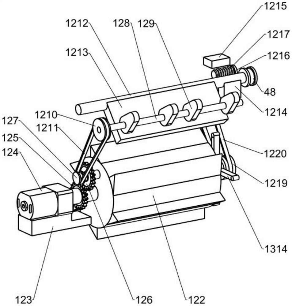
[0036] Such as Figure 1-3 As shown, on the basis of Embodiment 1, the crushing mechanism 12 includes a second rotating shaft 121, a crushing roller 122, a base 123, a reduction motor 124, a first gear 125, a second gear 126, a first pulley 127, a second Three rotating shafts 128, cam 129, second pulley 1210, first belt 1211, fourth rotating shaft 1212, first extrusion plate 1213, fixed block 1214, connecting block 1215, pin rod 1216, torsion spring 1217, third pulley 1218, the fourth pulley 1219 and the second belt 1220, the second rotating shaft 121 is rotatably connected between the two mounting plates 4, the second rotating shaft 121 is located between the stopper frame 10 and the second baffle plate 11, the second rotating shaft Crushing roller 122 is installed on 121, and base 123 is installed on the rear side wall top of rear side mounting plate 4, and the top of base 123 is equipped with decelerating motor 124 by bolt, and the output shaft of decelerating motor 124 is ...
Embodiment 3
[0043] Such as Figure 1-7As shown, on the basis of Embodiment 2, it also includes a first support plate 17, a fifth rotating shaft 18, a second support plate 19, a sixth rotating shaft 20, a transmission roller 21, a conveyor belt 22, a first bevel gear 23, The third support plate 24, the seventh rotating shaft 25, the second bevel gear 26, the fifth pulley 27, the second fixed frame 28, the servo motor 29, the sixth pulley 30, the third belt 31 and the feeding assembly, the second installation The top of the bottom frame 1 on the front side of the frame 301 is provided with a first support plate 17, and a fifth rotating shaft 18 is rotatably installed between the first support plate 17 and the second mounting frame 301, and the top of the bottom frame 1 on the left side of the first support plate 17 Two second support plates 19 are installed, and a sixth shaft 20 is rotatably installed between the two second support plates 19, and a transmission roller 21 is installed on the...
PUM
 Abstract
Description
Claims
Application Information
 - Generate Ideas
- Intellectual Property
- Life Sciences
- Materials
- Tech Scout
- Unparalleled Data Quality
- Higher Quality Content
- 60% Fewer Hallucinations
Browse by: Latest US Patents, China's latest patents, Technical Efficacy Thesaurus, Application Domain, Technology Topic, Popular Technical Reports.
© 2025 PatSnap. All rights reserved.Legal|Privacy policy|Modern Slavery Act Transparency Statement|Sitemap|About US| Contact US: help@patsnap.com


