Light beam displacement amplification technology

A technology of beam displacement and displacement, which is applied in the field of optical precision measurement and two-dimensional materials, can solve the problems that the amplification factor cannot be calculated, the application restrictions are many, and the amplification technology is lacking.

Pending Publication Date: 2021-04-27
NANKAI UNIV
View PDF0 Cites 1 Cited by
  • Summary
  • Abstract
  • Description
  • Claims
  • Application Information

AI Technical Summary

Problems solved by technology

[0003] At present, there are two main solutions for GH displacement and SHEL displacement. One is to use multiple reflections to increase the displacement, which has many application restrictions and cannot be widely promoted.
The second is to use the weak measurement technology to amplify the displacement. The weak measurement technology is currently the most widely used displacement measurement technology, but its displacement amplification factor affects many parameters, such as the incident angle, the angle between the front and rear selection states, and even the thickness of the sample. complex calculation
And when measuring complex refractive index materials such as two-dimensional materials, the amplification factor cannot be calculated, only the amplification displacement can be obtained but the real displacement of the material cannot be obtained
And the incident spot in the weak measurement technique is too large to measure the beam displacement of other microstructures such as mechanically exfoliated 2D materials with high-quality properties
Therefore, an amplification technique capable of directly measuring the beam displacement of two-dimensional materials is still lacking.

Method used


Image

  • Light beam displacement amplification technology
  • Light beam displacement amplification technology
  • Light beam displacement amplification technology

Examples


Embodiment 1

[0017] Amplification Factor and Resolution Measurement of Displacement Sensor and Displacement Amplification Technology

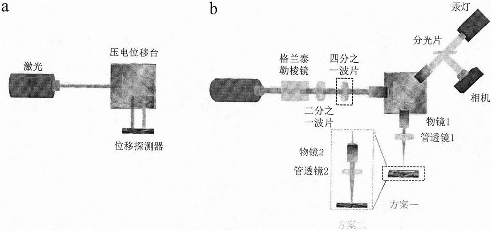
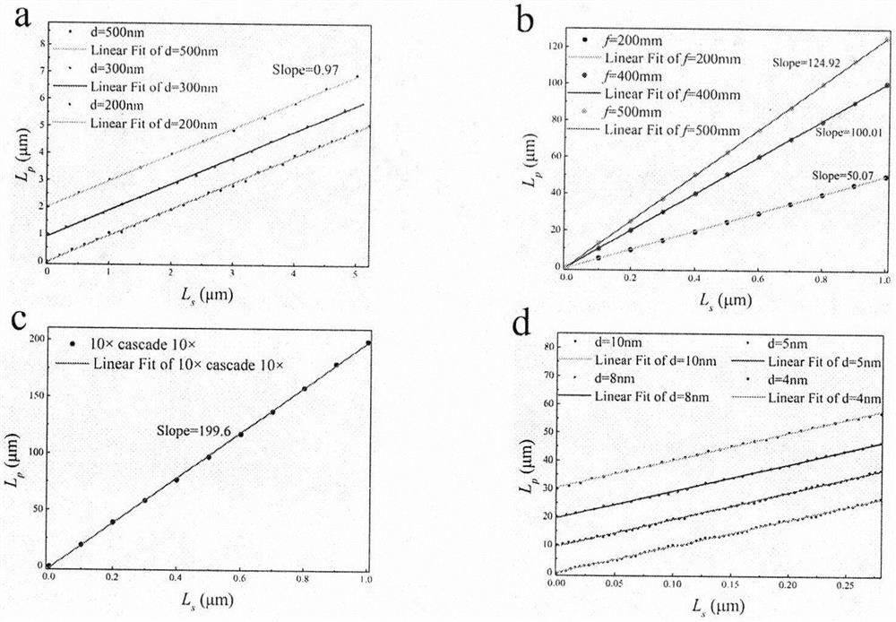
[0018] like figure 1 As shown in the optical path of a, the original resolution of the position sensor is determined by the piezoelectric stage, from figure 2 It can be seen from the data in a that the minimum resolution step size is 200nm, and the slope is the amplification factor value of 0.97, indicating that the original resolution of the position sensor is 200nm and the displacement is not amplified. figure 1 The b optical path is a schematic diagram of the optical path of the displacement amplification technology. We have two schemes. The first scheme is a red box. Only the objective lens 1 is used for displacement amplification, and the displacement amplification factor is changed by changing the focal length of the tube lens 1. figure 2 b is the data schematic diagram of the objective lens 1 in scheme 1 with a 50x objective lens, and the focal le...

Embodiment 2

[0020] Molybdenum disulfide SHEL displacement measurement

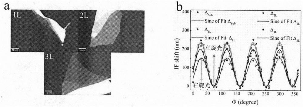
[0021] image 3 a shows the preparation of 1 to 3 layers of molybdenum disulfide samples on the K9 substrate by the method of mechanical exfoliation. Its thickness has been determined by atomic force microscopy and reflectance spectroscopy. image 3 b is the displacement of the base and 1-3 layers of SHEL. It can be seen that the displacement is the largest when the incident light is right-handed, and the smallest when the incident light is left-handed. And the displacement difference between right-handed light and left-handed light gradually decreases with the increase of the number of layers.

Embodiment 3

[0023] Black phosphorus GH shift measurement

[0024] Figure 4 a shows the microscopic image of black phosphorus, which has in-plane anisotropy, and its crystal orientation has been marked by the arrow. like Figure 4 As shown in a, we measured the GH displacement in different crystal orientations. The p-polarized light displacement and s-polarized light displacement are marked in the data graph. It can be seen that the GH displacement along the AC axis is greater than the displacement along the ZZ axis.


PUM

PropertyMeasurementUnit
Gain coefficientaaaaaaaaaa

Abstract

A light beam displacement amplification technology is based on an optical objective lens imaging principle and a high-sensitivity position sensor, displacement can be amplified by 200 times at most, the theoretical displacement resolution reaches 1 nm, incident light spots are converged by an objective lens, the light spots are smaller than 5 microns, and micro-area materials such as mechanical stripping two-dimensional materials can be measured. Incident light spots are polarized by the Glan-Taylor prism, the half-wave plate and the quarter-wave plate, then irradiate a sample and interact with the sample to generate transverse photon spin Hall effect displacement and longitudinal Goos Hansen displacement, the displacement is amplified by the collection objective lens, and the amplified displacement is measured by the position sensor. The amplification factor is only related to the multiple of the objective lens and the focal length of the corresponding tube lens, the real displacement of the light spot in the sample can be obtained by calculating the amplification factor, multiple collection objective lenses can be cascaded for multiple amplification; wherein the amplification factor is the product of the amplification factors of each objective lens and is constant once determined. Therefore, the light beam displacement measurement technology is a direct measurement technology.

Description

technical field [0001] The invention belongs to the field of optical precision measurement and two-dimensional materials, and relates to a direct measurement technology for detecting the nanoscale movement of light beams in two-dimensional materials by using the imaging principle of an optical objective lens and a high-precision position sensor. Background technique [0002] High-precision measurement of beam displacement measurement is of great significance in many aspects, such as the research of fundamental physical problems and the application of science and technology. The beam displacement is divided into the displacement of the propagation direction of the light and the spatial displacement of the vertical propagation direction. The propagation direction displacement can reach 10 based on the Laser Interferometer Gravitational-Wave Observatory (LIGO) -18 With a resolution of m, gravitational waves were observed in 2015 due to LIGO's high-precision measurements. High...

Claims


Application Information

Patent Timeline
Patent Type & Authority Applications(China)
IPC IPC(8): G01J1/42G01B11/02
CPCG01B11/02G01J1/4257
Inventor 刘智波李德康田建国
Owner NANKAI UNIV
Why Eureka
Try Eureka