Automatic calibrating device for standard metal measuring vessel

A standard metal gauge, automatic verification technology, applied in measuring devices, testing/calibrating devices, testing/calibrating volume flow, etc., can solve problems such as increased uncertainty, low efficiency, and easy water storage at the bottom valve position.

Pending Publication Date: 2021-04-27
辽宁省计量科学研究院
View PDF0 Cites 0 Cited by
  • Summary
  • Abstract
  • Description
  • Claims
  • Application Information

AI Technical Summary

Problems solved by technology

[0003] At present, domestic first-class standard metal gauges are used as the verification device of the main standard device, which are basically manual verification devices. Some technical institutions, enterprises and institutions have also tried to do automatic verification, but the technology of three-way valve and fine-tuning part is not enough. Mature, the position of the bottom valve is easy to store water, and all the water cannot be introduced into the measured device, resulting in the accuracy and repeatability of the first-class standard metal measuring device.
The fine-tuning part of the water level cannot solve the problem of accuracy well, and cannot be automated
[0004] Because the first-class measuring device is filled with water, the accuracy is high, and the water cannot be circulated. It is not recommended to use a pump to inject water into the first-class standard metal measuring device, which is prone to air bubbles. The difference in water level is required from the metal gauge to the metal gauge to be inspected. The existing first-class standard metal gauge water filling and downfilling devices are all done manually.
In this process, the efficiency is low, the temperature measurement is not accurate, and errors are prone to occur
The three-way valve at the bottom of the first-class standard gauge that plays a key role is a fixed structural component that cannot store water for a long time according to years of work experience and actual application in the work, as well as the national verification regulations. It involves water injection and water release. At the same time, the accuracy of measurement can only be guaranteed by filling with water, so the three-way valve is technically difficult to change, which leads to the fact that the verification work of standard metal measuring instruments is basically in a manual state, the detection efficiency is low, and errors are prone to occur during the detection process. Increased uncertainty
[0005] In addition, the existing first-class standard metal gauges verify the second-class, third-class or working standard metal gauges. Since the first-class standard metal gauges are used as the main standard to prevent air bubbles from affecting the accuracy of the verification, the water inlet method is required to be For water injection at the bottom, there is a certain height difference between the first-class standard metal measuring device and the tested device during the verification process. The tested device is at the bottom and the standard measuring device is at the top. The device is on the second floor. In order to ensure that the water level can reach the standard liquid level of the first-class standard metal gauge during the verification process, the water intake cannot fully reach the right position each time, and is generally higher than the liquid level, so it needs to be fine-tuned to the standard liquid level.
The valve at the existing fine-tuning port is a manual ball valve. When fine-tuning, it is necessary to manually go up to the second floor for visual inspection. The liquid level pipe is manually adjusted to the standard liquid level.
At least three verifications are required to complete the verification work of a metal measuring instrument, which takes a long time and is inefficient, and the human error of each verification is relatively large

Method used


Image

  • Automatic calibrating device for standard metal measuring vessel
  • Automatic calibrating device for standard metal measuring vessel
  • Automatic calibrating device for standard metal measuring vessel

Examples


Embodiment Construction

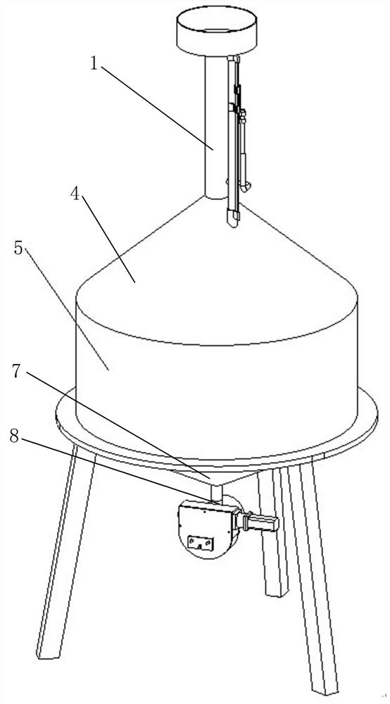
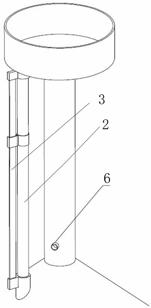
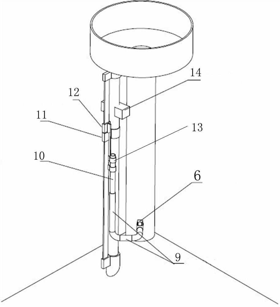
[0034] Such as Figure 1-9 As shown, the present invention includes an upper cone, a cylindrical body and a lower cone connected to each other. It is characterized in that the upper end of the upper cone is connected with a metering neck and a liquid level tube, and the liquid level tube is provided with a metering neck scale. The control valve on the neck is connected with a three-way valve at the lower end of the lower cone.

[0035] The end of the spool of the three-way valve far away from the valve port is fixedly connected with a gear. The gear is connected to a screw meshing transmission. The screw is fixed on the outer wall of the three-way valve through the mounting frame, and the screw can rotate relative to the mounting frame. Driven by a stepping motor; the stepping motor acts to drive the screw connected to it to rotate, the screw is meshed with the gear for transmission, and the gear rotates accordingly, driving the valve core to rotate.

[0036] The control valv...


PUM


Abstract

The invention belongs to the technical field of capacity measurement testing, and particularly relates to an automatic calibrating device for a standard metal measuring vessel; wherein an overflow device with the fine adjustment opening overflows redundant water to be parallel to the standard liquid level to achieve the fine adjustment function, and the functions of water injection, stopping and stopping after water discharging can be achieved. The device comprises a control valve arranged on a metering neck, and the lower end of a lower cone is connected with a three-way valve. A gear is fixedly connected outside the end, away from the valve port, of the valve element of the three-way valve, the gear is in engaged transmission connection with a screw, the screw is fixed to the outer wall of the three-way valve through an installation frame and can rotate relative to the installation frame, and one end of the screw is driven by a stepping motor; the control valve adopts an electric valve, the metering neck is connected with a first end of a connecting hose through the electric valve, a second end of the connecting hose is communicated with a first end of a glass tube, and a second end of the glass tube is fixed on a scale of the metering neck through a vernier scale connecting piece.

Description

technical field [0001] The invention belongs to the technical field of capacity measurement and testing, in particular to an automatic verification device for standard metal measuring instruments. Background technique [0002] Standard metal gauges are widely used in the flow and capacity measurement of fuel dispensers, volumetric tubes, flowmeters, etc. The objects to be checked involve people's livelihood and trade settlement. verification is very important. The standard metal gauge automatic verification device uses the first-class standard metal gauge as the main standard, usually used as the standard device and equipment for the traceability of the second-class, third-class or working standard metal gauge. [0003] At present, domestic first-class standard metal gauges are used as the verification device of the main standard device, which are basically manual verification devices. Some technical institutions, enterprises and institutions have also tried to do automatic...

Claims


Application Information

Patent Timeline
IPC IPC(8): G01F25/00
CPCG01F25/0084G01F25/10Y02E30/30
Inventor 张弦陆科邹海波韩博
Owner 辽宁省计量科学研究院
Why Eureka
Try Eureka