
Pure oxygen smelting device of flash furnace and using method of pure oxygen smelting device

A smelting device and flash furnace technology, which is applied in the direction of furnace control device, furnace, furnace cooling, etc., can solve the problem that the temperature of the flue gas inlet of the electrostatic precipitator is too high, the blower load cannot be fully utilized, and the high-load production of the flash furnace is limited To achieve the effect of optimizing the heat distribution structure, reducing the total heat intensity, and reducing the number of times of coke cleaning

Pending Publication Date: 2021-04-27
广西金川有色金属有限公司 +1
View PDF10 Cites 0 Cited by
  • Summary
  • Abstract
  • Description
  • Claims
  • Application Information

AI Technical Summary

Problems solved by technology

[0002] In the traditional flash furnace for copper smelting, the smelting oxygen-enriched concentration is controlled at about 85%, and secondary air needs to be supplied. The operating cost of the blower is high, and the load of the blower cannot be fully utilized, resulting in waste of resources
After the flow rate of materials discharged into the flash furnace increases, the production load increases, the oxygen supply cannot be supplied in time, and flue gas is generated. Due to the unreasonable distribution of heat between the flue gas and the melt, the top and the top of the flash furnace sedimentation tank There are a series of problems such as the red burning phenomenon of the end wall, the high temperature of the flue gas inlet of the electric precipitator, and the large amount of flue gas entering the acid system; in order to ensure the discharge temperature of the melt, the reaction tower not only cannot perform self-heating reaction , fuel needs to be replenished. On the one hand, fuel consumption remains high, and on the other hand, a vicious cycle is formed. The temperature of the flue gas system is extremely high, and the boiler soot is melted and bonded, which limits the continuation of high-load production of the flash furnace.

Method used


Image

  • Pure oxygen smelting device of flash furnace and using method of pure oxygen smelting device
  • Pure oxygen smelting device of flash furnace and using method of pure oxygen smelting device
  • Pure oxygen smelting device of flash furnace and using method of pure oxygen smelting device

Examples


Embodiment 1

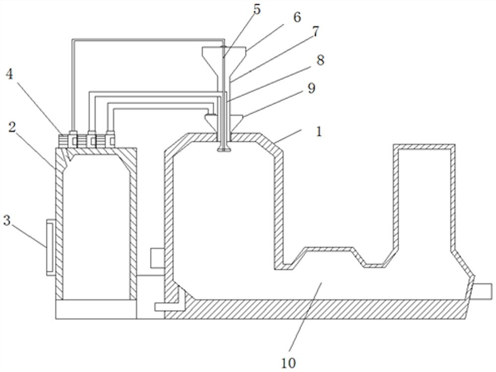
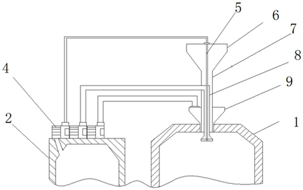
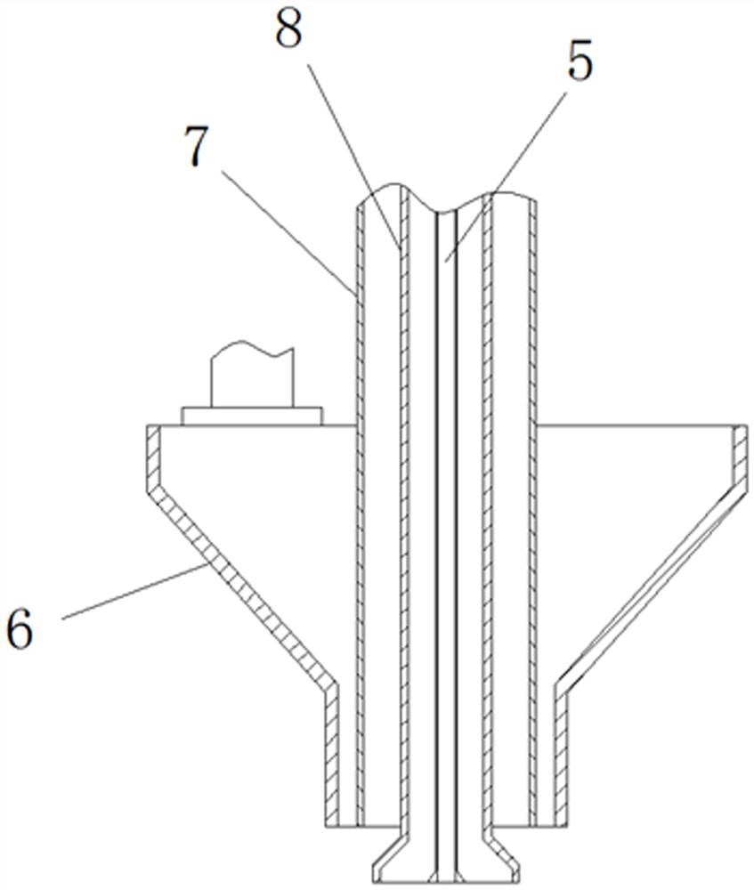
[0024] like Figure 1-4 As shown, a flash furnace pure oxygen smelting device of this embodiment includes a furnace body and a material supply device 6. The top of the reaction tower 1 of the furnace body is provided with a nozzle with an opening downward; the bottom of the nozzle is The opening extends into the reaction tower 1; the nozzle includes a central oxygen pipeline 5, a material pipeline 7, a dispersed oxygen pipeline 8 and a process oxygen pipeline 9, and a material pipeline 7 is installed in the process oxygen pipeline 9, and a dispersed oxygen pipeline is installed in the material pipeline 7. Pipeline 8, a central oxygen pipeline 5 is installed in the dispersed oxygen pipeline 8; the top opening of the material pipeline 7 is connected to the material supply device 6; it also includes an oxygen tank 2; the top of the oxygen tank 2 is provided with three oxygen pumps 4, each Two oxygen pumps 4 are respectively connected to the central oxygen pipeline 5, the disperse...

Embodiment 2

[0027] The difference between this embodiment and Embodiment 1 is that: the bottom of the oxygen dispersing pipeline 8 is provided with a dispersing nozzle, the opening of the nozzle is inclined outward, and the central oxygen pipeline 5 passes through the dispersing nozzle. The dispersing nozzle makes most of the oxygen and materials discharged into the process oxygen pipeline divergent and sprays, further balances the oxygen supply ratio of the material reaction, and reduces flue gas emissions.

[0028] The working principle of this embodiment is the same as that of Embodiment 1.

Embodiment 3

[0030] The difference between this embodiment and Embodiment 2 lies in that divergent injection holes are evenly arranged on the outside of the dispersing nozzle. The divergent injection holes are evenly arranged on the outside of the dispersing nozzle, which provides a dispersing nozzle that injects oxygen laterally, and meets the requirements of high-load production, more material discharge and process oxygen pipeline discharge, and higher spray intensity.

[0031] The working principle of this embodiment is the same as that of Embodiment 2.


PUM


Abstract

The invention discloses a pure oxygen smelting device of a flash furnace. The pure oxygen smelting device of the flash furnace comprises a furnace body and a material supply device, and further comprises an oxygen tank, wherein a nozzle with a downward opening is arranged at the top of a reaction tower of the furnace body; three oxygen pumps are arranged at the top of the oxygen tank; each oxygen pump is connected with a central oxygen pipeline, a dispersed oxygen pipeline and a process oxygen pipeline through pipelines respectively; a control panel is mounted at the bottom of the oxygen tank; a flow meter is mounted on a material pipeline; the control panel is electrically connected with the oxygen pumps and the flow meter respectively; and a water cooling pipeline is mounted on the outer side of a sedimentation tank of the furnace body. According to the pure oxygen smelting device, the three independent oxygen supply pumps are arranged to provide oxygen amounts with different proportions for the central oxygen pipeline, the dispersed oxygen pipeline and the process oxygen pipeline respectively; the flow meter is used for metering the amount of materials discharged into the reaction furnace; a signal is transmitted to the control panel and an oxygen supply demand amount is judged; and output power of the oxygen pumps is controlled respectively and functional adjustment of an oxygen introducing amount is realized, so that the materials react to obtain sufficient oxygen and flue gas is reduced.

Description

technical field [0001] The invention belongs to the technical field of flash furnace smelting, and in particular relates to a flash furnace pure oxygen smelting device and a use method thereof. Background technique [0002] In the traditional copper smelting flash furnace, the smelting oxygen-enriched concentration is controlled at about 85%, and secondary air needs to be supplied. The operating cost of the blower is high, and the load of the blower cannot be fully utilized, resulting in waste of resources. After the flow rate of materials discharged into the flash furnace increases, the production load increases, the oxygen supply cannot be supplied in time, and flue gas is generated. Due to the unreasonable distribution of heat between the flue gas and the melt, the top and the top of the flash furnace sedimentation tank There are a series of problems such as the red burning phenomenon of the end wall, the high temperature of the flue gas inlet of the electric precipitator...

Claims


Application Information

Patent Timeline
IPC IPC(8): F27D7/02F27D9/00F27D3/00F27D19/00C22B15/00
CPCF27D7/02F27D9/00F27D3/00F27D19/00C22B15/0047F27D2007/023F27D2009/0013F27D2019/0034
Inventor 张建平许俊张更生王取敏王博陈文武安志鹏李钰平
Owner 广西金川有色金属有限公司
Learn More