Automatic control manipulator

A technology of manipulators and rotating grooves, applied in the field of manipulators, can solve problems such as difficult adjustment of device angles, cumbersome operations, and complex structures, and achieve the effects of firm structure of parts, firm holding of objects, and increased precision

Inactive Publication Date: 2021-04-27
HENAN POLYTECHNIC UNIV
View PDF8 Cites 1 Cited by
  • Summary
  • Abstract
  • Description
  • Claims
  • Application Information

AI Technical Summary

Problems solved by technology

[0005] The purpose of the present invention is to provide an automatic control manipulator to solve the problems of complex structure, cumbersome operation, difficult adjustment of the device angle and inflexibility of the general manipulator proposed in the above-mentioned background technology.

Method used


Image

  • Automatic control manipulator
  • Automatic control manipulator
  • Automatic control manipulator

Examples


Embodiment Construction

[0024] The following will clearly and completely describe the technical solutions in the embodiments of the present invention with reference to the accompanying drawings in the embodiments of the present invention. Obviously, the described embodiments are only some, not all, embodiments of the present invention. Based on the embodiments of the present invention, all other embodiments obtained by persons of ordinary skill in the art without making creative efforts belong to the protection scope of the present invention.

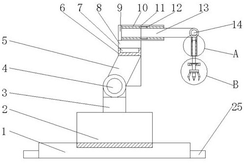
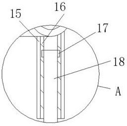
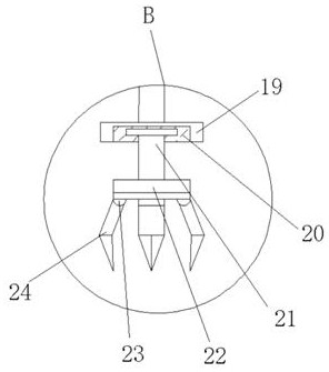
[0025] see Figure 1-5 , the present invention provides a technical solution: an automatic control manipulator, including a base 1, a support plate 2, a support column 3, a first rotating shaft 4, a rotating column 5, a first rotating groove 6, a first rotating block 7, and a connecting column 8. Chassis 9, nesting rod 10, first sliding groove 11, first sliding block 12, sliding rod 13, second rotating shaft 14, adjustment rod 15, second sliding groove 16, sec...


PUM


Abstract

The invention belongs to the technical field of manipulators, and particularly relates to an automatic control manipulator, which comprises a base, a rotating column and an adjusting rod; a supporting disc is mounted above the base, and a supporting column is mounted at the top of the supporting disc; a first rotating shaft is mounted above the supporting column, and the rotating column is mounted at the top of the first rotating shaft; a first rotating groove is reserved above the rotating column, and a first rotating block is arranged in the first rotating groove; a connecting column is installed at the top of the first rotating block, and a chassis is installed above the connecting column; and a nesting rod is installed on the right side of the outer wall of the chassis, and a first sliding groove is reserved on the inner wall of the nesting rod. Compared with an existing manipulator, the automatic control manipulator provided by the invention is simple in structure, the operation difficulty is reduced, a user can operate the automatic control manipulator easily and conveniently, the user can freely adjust the angle of the automatic control manipulator, the automatic control manipulator moves flexibly, great convenience is provided for the user, and user groups are greatly increased.

Description

technical field [0001] The invention relates to the technical field of manipulators, in particular to an automatic control manipulator. Background technique [0002] The manipulator is the earliest industrial robot and the first modern robot. It can replace the heavy labor of people to realize the mechanization and automation of production, and can operate in harmful environments to protect personal safety. Therefore, it is widely used in machinery manufacturing, metallurgy, In the departments of electronics, light industry and atomic energy, the automatic control manipulator is an automatic device that increases the automation structure and reduces the manual operation on the basis of the original manipulator. [0003] The complex structure of the manipulators on the market makes the user cumbersome to operate, and it is difficult to adjust the angle of the device. The movement of the device is not flexible enough, which makes the user a lot of inconvenience when using the ...

Claims


Application Information

Patent Timeline
Patent Type & Authority Applications(China)
IPC IPC(8): B25J15/00B25J18/02
CPCB25J15/00B25J18/02B25J18/025
Inventor 陈春朝刘义贾芳王耿孙东红
Owner HENAN POLYTECHNIC UNIV
Why Eureka
Try Eureka