
Centrifugal device for processing stem cell exosome

A centrifuge device and exosome technology, applied in centrifuges and other directions, can solve the problems of inability to centrifuge control, waste of manpower and material resources, and inability to separate exosomes, and achieve the effect of improving efficiency and improving centrifugal efficiency.

Inactive Publication Date: 2021-04-27
菲尔生物工程技术有限公司
View PDF0 Cites 1 Cited by
  • Summary
  • Abstract
  • Description
  • Claims
  • Application Information

AI Technical Summary

Problems solved by technology

[0003] The traditional centrifugation of exosomes from stem cells is usually manually operated. During the operation, the speed of centrifugation is often not accurately controlled, and exosomes are often not separated well. Secondary manual operations are often required, which wastes a lot of time. Manpower and material resources, in order to solve the above problems, it is necessary to design a new type of centrifugal device for stem cell exosome processing

Method used


Image

  • Centrifugal device for processing stem cell exosome
  • Centrifugal device for processing stem cell exosome
  • Centrifugal device for processing stem cell exosome

Examples


Embodiment 1

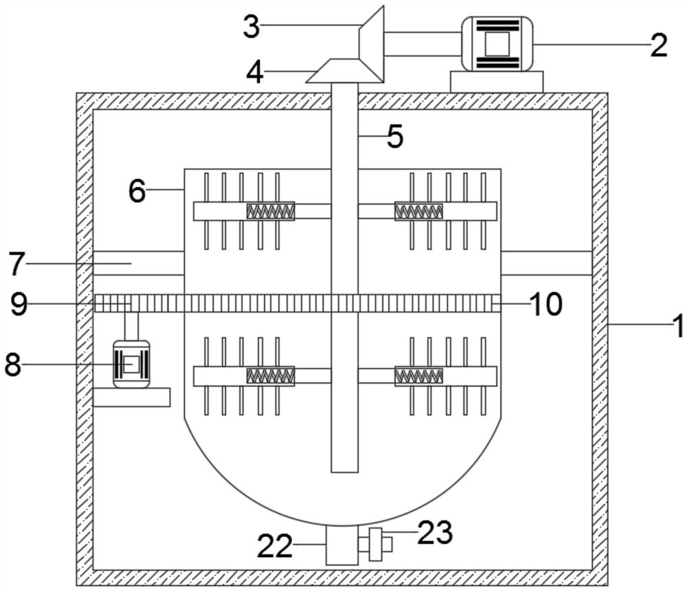
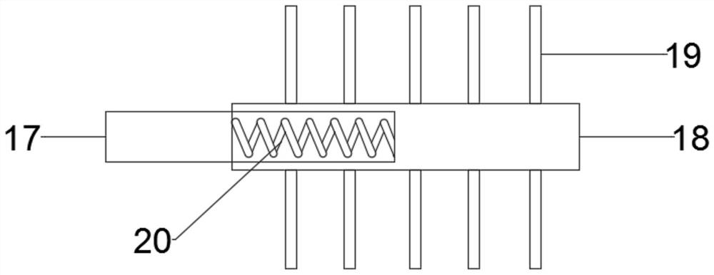
[0021] see Figure 1~2 , in an embodiment of the present invention, a centrifugal device for stem cell exosome processing, comprising a device main body 1, a side wall of the device main body 1 is fixedly provided with a mounting plate, and a second motor 8 is fixedly provided on the mounting plate , the rotating part of the second motor 8 is fixedly connected with a gear 9, and a bracket 7 is fixedly arranged in the main body 1 of the device, and a fixed cylinder 6 is rotatably arranged on the bracket 7, and the outer surface of the fixed cylinder 6 is fixedly arranged There is a ring gear 10, the ring gear 10 is meshed with the gear 9, the bottom of the fixed cylinder 6 is provided with a discharge pipe 22, and the discharge pipe 22 is fixedly provided with a control valve 23;

[0022] Further, the top of the main body 1 of the device is fixedly provided with a first motor 2, the rotating part of the first motor 2 is fixedly provided with a first bevel gear 3, and a second b...

Embodiment 2

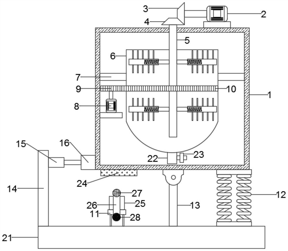
[0024] see image 3 , The difference between this embodiment and Embodiment 1 is that it also includes a shaking mechanism, a support plate 21 is fixedly arranged below the device main body 1, and a fixed plate 14 is fixedly arranged on the support plate 21, and the fixed plate 14 The top is fixedly provided with an electric telescopic rod 15, and the bottom of the device main body 1 is fixedly provided with a fixed block 16 at a position corresponding to the electric telescopic rod 15, and the end of the telescopic rod 15 of the electric telescopic rod 15 is inserted into the fixed block 16. The bottom of the main body 1 of the device is fixedly provided with a magnetic plate 24, and a plurality of support rods are evenly distributed on the position corresponding to the magnetic plate 24 on the support plate 21. The end of the support rod away from the support plate 21 is fixedly provided with a mounting base 11, so that A third motor 25 is fixedly installed on the mounting b...


PUM


Abstract

The invention discloses a centrifugal device for processing the stem cell exosome. The centrifugal device comprises a device body, a mounting plate is fixedly arranged on one side wall in the device body, a second motor is fixedly arranged on the mounting plate, a rotating part of the second motor is fixedly connected with a gear, and a support is further fixedly arranged in the device body. A fixing cylinder is rotationally arranged on the support, and a gear ring is fixedly arranged on the outer surface of the fixing cylinder. A first motor is fixedly arranged at the top of the device body, a first bevel gear is fixedly arranged on a rotating part of the first motor, a second bevel gear is connected to the first bevel gear in an engaged mode, the stem cell exosome is put into the fixing cylinder. And at the moment, the second motor rotates to drive the gear to rotate, the gear rotates to drive the gear ring to rotate, then the fixing cylinder is driven to rotate, and therefore the stem cell exosome is centrifuged; and meanwhile, the first motor rotates to drive the first bevel gear to rotate, and the first bevel gear rotates to drive the second bevel gear to rotate.

Description

technical field [0001] The invention relates to a centrifugal device, in particular to a centrifugal device for processing stem cell exosomes. Background technique [0002] Exosomes refer to small membrane vesicles containing complex RNA and proteins. Today, they specifically refer to disc-shaped vesicles with a diameter of 40 to 100 nanometers. All cultured cell types can secrete exosomes, and exosomes Occurs naturally in body fluids, including blood, saliva, urine, cerebrospinal fluid and breast milk. [0003] The traditional centrifugation of exosomes from stem cells is usually manually operated. During the operation, the speed of centrifugation is often not accurately controlled, and the exosomes are often not separated well. Secondary manual operations are often required, which wastes a lot of time. Manpower and material resources, in order to solve the above problems, it is necessary to design a new type of centrifugal device for stem cell exosome processing. Conten...

Claims


Application Information

Patent Timeline
Patent Type & Authority Applications(China)
IPC IPC(8): B04B5/00B04B15/00B04B7/00
CPCB04B5/00B04B7/00B04B15/00
Inventor 朱学义刘岩
Owner 菲尔生物工程技术有限公司
Learn More