Volatile gas purification treatment system

A volatile gas purification treatment technology, applied in chemical instruments and methods, dispersed particle separation, separation methods, etc., can solve problems such as environmental pollution, failure to meet the needs of volatile gas recovery, waste of resources, etc.

Inactive Publication Date: 2021-04-27
高京拴
View PDF0 Cites 0 Cited by
  • Summary
  • Abstract
  • Description
  • Claims
  • Application Information

AI Technical Summary

Problems solved by technology

[0002] At present, with the expansion of industrial production scale, the volatile gas produced by industrial production is gradually increasing. If the volatile gas is directly discharged into the air, it will not only cause environmental pollution, but also lead to waste of resources. to recycle
The existing volatile gas recovery method mainly absorbs volatile gas through solvents such as biodiesel and kerosene, but the recovery efficiency is still low, which cannot meet the needs of the existing volatile gas recovery

Method used


Image

  • Volatile gas purification treatment system
  • Volatile gas purification treatment system
  • Volatile gas purification treatment system

Examples


Embodiment 1

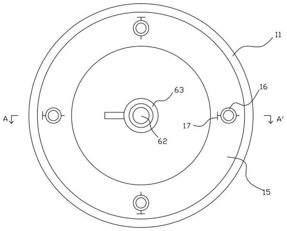
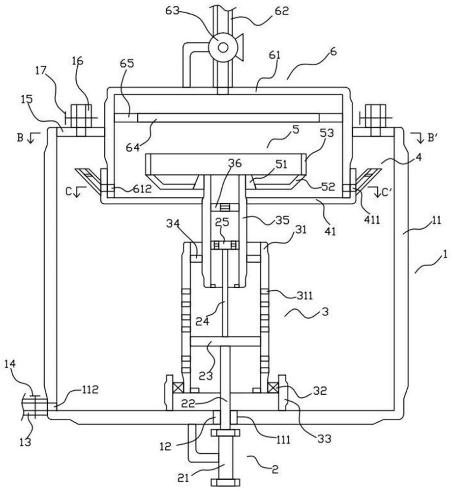
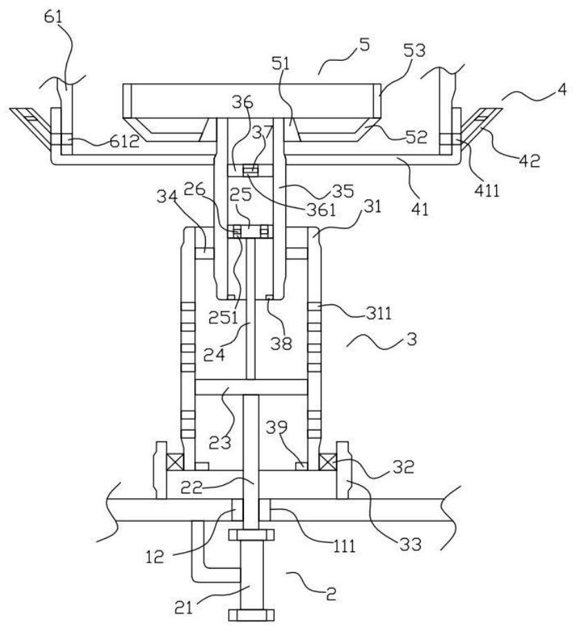
[0027] Such as Figure 1 to Figure 6 As shown, the volatile gas purification system of the present invention includes a housing structure 1, a driving structure 2 disposed on the housing structure 1, a rotating structure 3 disposed in the housing structure 1, and a rotating structure disposed on the rotating structure 3. The frame structure 4 , the spraying structure 5 arranged on the upper end of the rotating structure 3 , and the covering frame structure 6 located above the rotating structure 3 .

[0028] Such as figure 1 , figure 2 , Figure 4 , Figure 5 As shown, the housing structure 1 includes a housing 11, a sealing block 12 disposed on the lower wall of the housing 11, a discharge pipe 13 disposed outside the housing 11, a first valve 14 disposed on the discharge pipe 13, and a A fixed plate 15 at the upper end of the inner cavity of the housing 11 , a plurality of exhaust pipes 16 arranged above the fixed plate 15 , and a second valve 17 arranged on the exhaust ...

Embodiment 2

[0040] Embodiment two: if Figure 7 and Figure 8 As shown, the structure of the second embodiment of the volatile gas purification treatment system of the present invention is basically the same as that of the first embodiment, the only difference being that the second embodiment of the volatile gas purification treatment system of the present invention also includes a rotating Stirring structure 7 on structure 3. The stirring structure 7 is provided with several and evenly distributed, and the stirring structure 7 includes a first spring 71, a positioning rod 72 arranged at the end of the first spring 71, an abutment rod 73 arranged at the end of the positioning rod 72, and a positioning rod 72 arranged at the end of the positioning rod 72. The moving rod 74 on the top, the stirring rod 75 arranged at both ends of the moving rod 74, the second spring 76 arranged on the moving rod 74. One end of the first spring 71 is fixedly connected to the outer peripheral surface of the...


PUM


Abstract

A volatile gas purification treatment system comprises a shell structure and a driving structure, the shell structure comprises a shell, the volatile gas purification treatment system further comprises a rotating structure, a rotating frame structure and a covering frame structure, and the rotating structure comprises an inner frame; and the rotating frame structure comprises a rotating frame, an inclined pipe arranged on the outer circumferential face of the rotating frame and a sponge block arranged in the inclined pipe, and the inner frame penetrates through the inner surface and the outer surface of the rotating frame and is fixedly connected with the rotating frame. Through a driving structure, namely an air cylinder, rotation of the rotating structure and one-way upward flowing of liquid can be achieved at the same time, on one hand, rotation of the rotating structure can drive the rotating frame structure to rotate so as to achieve periodic communication of the seventh through hole and the ninth through hole, and therefore the atmospheric pressure can be increased periodically; and liquid can be sprayed out dispersedly, contact with gas is enhanced, and meanwhile, liquid in the sponge block can be thrown out as soon as possible, so that new liquid can be absorbed to enhance gas absorption.

Description

technical field [0001] The invention relates to the technical field of volatile gas treatment, in particular to a volatile gas purification treatment system. Background technique [0002] At present, with the expansion of industrial production scale, the volatile gas produced by industrial production is gradually increasing. If the volatile gas is directly discharged into the air, it will not only cause environmental pollution, but also lead to waste of resources. to recycle. The existing volatile gas recovery method mainly absorbs volatile gas through solvents such as biodiesel and kerosene, but the recovery efficiency is still low, which cannot meet the needs of the existing volatile gas recovery. [0003] Therefore, it is necessary to provide a new technical solution to overcome the above defects. Contents of the invention [0004] The object of the present invention is to provide a volatile gas purification treatment system that can effectively solve the above techni...

Claims


Application Information

Patent Timeline
IPC IPC(8): B01D53/18
CPCB01D53/1487B01D53/1493B01D53/18B01D53/185B01D2252/205
Inventor 高京拴庄静梅
Owner 高京拴
Why Eureka
Try Eureka