
Multi-point parallel synchronous driving solar tracking system

A solar tracking and synchronous drive technology, applied in solar heating systems, mobile/directional solar collectors, solar thermal energy, etc., can solve problems such as inability to achieve multi-point co-locking function, inconvenient power station design, and cracking of solar modules. , to achieve the effect of improving reliability and stability, convenient operation and maintenance, and reducing jitter

Pending Publication Date: 2021-04-23
ARCTECH SOLAR HLDG CO LTD
View PDF0 Cites 0 Cited by
  • Summary
  • Abstract
  • Description
  • Claims
  • Application Information

AI Technical Summary

Problems solved by technology

Since the distance from the driving point to the edge of the system in a single solar tracking system is generally more than ten meters or even tens of meters in length, under the action of gusts of wind, risks such as deformation and resonance are likely to occur, so that it is impossible to achieve multi-point common use in strong winds. Locking function, the deformation and vibration of the system will cause damage to the system, and long-term operation will also cause risks such as cracks on the solar modules carried on it
Moreover, in current practical applications, a single set of solar tracking system can only meet up to three 1500V photovoltaic strings, which is very inconvenient for power station design

Method used


Image

  • Multi-point parallel synchronous driving solar tracking system
  • Multi-point parallel synchronous driving solar tracking system
  • Multi-point parallel synchronous driving solar tracking system

Examples


Embodiment 1

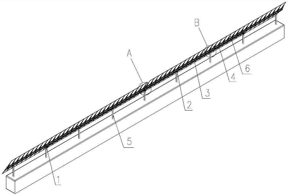
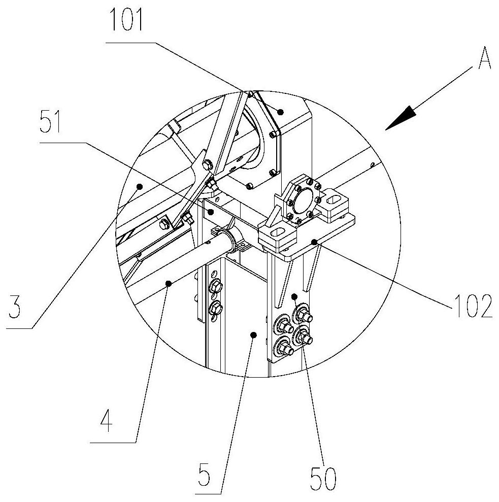
[0053] Such as Figure 1~4 As shown, it is a multi-point parallel synchronous drive solar tracking system, including a main shaft 3 and a plurality of columns 5 for supporting the main shaft 3, and the main shaft 3 is used for fixing solar modules 6;

[0054] It also includes a multi-point parallel synchronous driving device arranged on the main shaft 3, and the multi-point parallel synchronous driving device includes a drive mechanism 1 and several stages of driven mechanisms 2 connected by transmission;

[0055] The first power output end of the drive mechanism 1 is rotationally connected to the main shaft 3, and the main shaft 3 is used as the power output shaft; the second power output end of the drive mechanism 1 is fixed below the main shaft 3 and is axially parallel to the main shaft 3;

[0056] Several stages of the driven mechanism 5 are arranged at intervals along the main shaft 3, the second power output end of the driving mechanism 1 is connected to the power input...

Embodiment 2

[0061] Such as Figure 1~4 As shown, it is a multi-point parallel synchronous drive solar tracking system, including a main shaft 3 and a plurality of columns 5 for supporting the main shaft 3, and the main shaft 1 is used for fixing solar modules 6;

[0062] It also includes a multi-point parallel synchronous driving device arranged on the main shaft 3, and the multi-point parallel synchronous driving device includes a drive mechanism 1 and several stages of driven mechanisms 2 connected by transmission;

[0063] The first power output end of the drive mechanism 1 is rotationally connected to the main shaft 3, and the main shaft 3 is used as the power output shaft; the second power output end of the drive mechanism 1 is arranged below the main shaft 3 and is axially parallel to the main shaft 3;

[0064] The drive mechanism 1 includes a worm gear transmission unit I10 fixed on the column 5, and a transmission gear 11 as a second power output end; the worm gear transmission un...

Embodiment 3

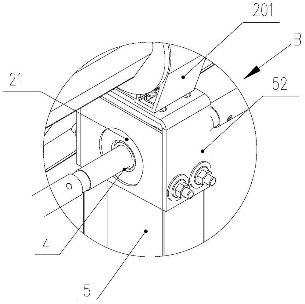
[0082] In this embodiment, on the basis of Embodiment 1 or 2, it should be noted that, in addition to the column 5 that supports the main shaft 3, the driving mechanism 1 and the driven mechanism 2 synchronously, other columns that independently support the main shaft can also be provided. 5. Such as Figure 5a , 5b As shown, the top of this type of column 5 is fixedly connected with the column top seat 52; the main shaft 3 is passed through the bearing, and the bearing is installed in the bearing race 30; the column top seat 52 is connected with the bearing race 30 is fixedly connected to realize the rotatable support directly to the main shaft 3. In practical application, the top of the column 5 is provided with an up and down adjustable row of holes IIIC, the column top 51 is set as a U-shaped bending part, and a set of fixing holes IIID are arranged oppositely on the two vertical surfaces of the column top 51 The relative height adjustment of the column 5 and the column...


PUM


Abstract

The invention discloses a multi-point parallel synchronous driving solar tracking system. The system comprises a main shaft and a plurality of upright posts for supporting the main shaft; the main shaft is used for fixedly arranging a solar assembly; the system further comprises a multi-point parallel synchronous driving device arranged on the main shaft; the multi-point parallel synchronous driving device comprises a driving mechanism and a plurality of stages of driven mechanisms which are in transmission connection; a first power output end of the driving mechanism is rotationally connected with the main shaft, with the main shaft serving as a power output shaft; a second power output end of the driving mechanism is arranged below the main shaft and is axially parallel to the main shaft; the multiple stages of driven mechanisms are arranged at intervals along the main shaft; the second power output end of the driving mechanism is in transmission connection with the power input ends of the adjacent driven mechanisms in the axial direction; and every two adjacent stages of driven mechanisms are in transmission connection in the axial direction; the power output end of any stage of driven mechanism is rotationally connected with the main shaft; and therefore, the driving mechanism and the driven mechanisms are in transmission fit to realize multi-point parallel synchronous driving rotation of the main shaft. The system can achieve multi-point locking, and remarkably improve wind resistance.

Description

technical field [0001] The invention belongs to the technical field of photovoltaic supports, and in particular relates to a multi-point parallel synchronous drive solar tracking system. Background technique [0002] At present, the single-drive tracking system is widely used in the drive tracking system of photovoltaic brackets, which is driven by a single point of drive mechanism such as a reducer, a push rod, and a linear actuator. In this way, a free long cantilever structure is formed except for the drive point, which is prone to strong winds. The lower free long cantilever is distorted, and the longer the cantilever, the more serious the superposition of the distortion will cause the risk of damage to the components and brackets. At the same time, the low natural frequency will also increase the risk of resonance. Specifically, in the single-axis tracking system, except for the driving point which is a fixed locking point under the action of strong wind, other points o...

Claims


Application Information

Patent Timeline
IPC IPC(8): H02S20/32F24S30/425F24S50/20
CPCF24S30/425F24S50/20H02S20/32Y02E10/47Y02E10/50
Inventor 王士涛俞正明童舜勇陈井强王敏杰
Owner ARCTECH SOLAR HLDG CO LTD
Learn More