
Sealing structure and sealing method of non-welded metal plate single battery

A sealing structure, single cell technology, applied in fuel cell parts, fuel cells, sealing/supporting devices, etc., can solve the problems of high scrap rate, difficulty in dispensing, affecting sealing performance and reliability, etc.

Pending Publication Date: 2021-04-23
FUJIAN YANAN ELECTRIC MACHINE
View PDF0 Cites 5 Cited by
  • Summary
  • Abstract
  • Description
  • Claims
  • Application Information

AI Technical Summary

Problems solved by technology

If the tooling is not used for fitting, once the sealing ring is misaligned, it will easily lead to sealing failure
[0010] If the method of dispensing glue is used to directly apply glue on the metal plate, there will be the following problems: 1. After the bipolar plate is welded, there will be a certain deformation. It leads to the change of the thickness of the sealing ring after dispensing, which affects the performance and reliability of the sealing; 2. The tooling design is very complicated, resulting in low dispensing production efficiency, and the manufacturing cost of a full set of tooling is not a small expense; 3. Sealing ring dispensing There will be a certain degree of deviation in the width and thickness of the glue start point, glue collection point, and all joint sealing rings, resulting in very difficult dispensing and high scrap rate; 4. It takes a long time after one side of glue is completed. After curing (1-3 hours), the dispensing work on the other side can be carried out, which requires a large work site to place semi-finished products

Method used


Image

  • Sealing structure and sealing method of non-welded metal plate single battery
  • Sealing structure and sealing method of non-welded metal plate single battery
  • Sealing structure and sealing method of non-welded metal plate single battery

Examples


Embodiment Construction

[0033] The present invention will be further described in detail below in conjunction with the accompanying drawings and specific embodiments.

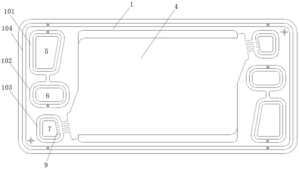
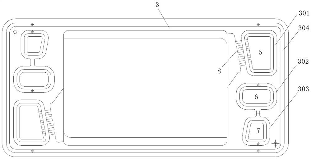
[0034] Such as Figure 1-6 As shown, this embodiment provides a sealed structure of a non-welded metal plate single cell, including a single cell formed by stacking an anode plate 1, a membrane electrode 2 and a cathode plate 3, and the membrane electrode is formed by a middle The membrane electrode main body 201 and the membrane electrode frame 202 on its outer periphery are composed. The middle part of the single cell is a flow field area 4 with an anode flow field 401, a cooling flow field 402 and a cathode flow field 403. The left and right sides of the flow field area 4 are There are air main passages 5, cooling main passages 6 and hydrogen main passages 7 communicated with the cathode flow field, cooling flow field and anode flow field respectively; the air main passages, cooling main passages and hydrogen main passages on the a...


PUM


Abstract

The invention relates to a sealing structure and a sealing method of a non-welded metal plate single cell, the sealing structure comprises a single cell formed by stacking an anode plate, a membrane electrode and a cathode plate together, an air main channel is communicated with a cathode flow field through an air side air inlet duct and a negative plate air side boss, and a hydrogen main channel is communicated with an anode flow field through a hydrogen side gas inlet duct by penetrating through a hydrogen side boss of an anode plate; the anode plate air side boss is communicated with the anode plate water side boss through a first channel, a first communication hole is formed in a membrane electrode frame between the anode plate water side boss and the cathode plate water side boss, and the cathode plate water side boss is communicated with the cathode plate hydrogen side boss through a second channel; and sealing rings are formed in the anode plate air side boss, the first channel, the anode plate water side boss, the cathode plate water side boss, the second channel and the cathode plate hydrogen side boss through integrated glue injection. The sealing structure and the sealing method are high in reliability, low in production cost and high in production efficiency.

Description

technical field [0001] The invention belongs to the technical field of fuel cells, and in particular relates to a sealing structure and a sealing method of a non-welded metal plate single cell. Background technique [0002] A hydrogen fuel cell is a real-time power generation device that directly converts chemical energy into electrical energy. At present, there have been many successful demonstration cases of fuel cells in the automotive field. Compared with energy storage batteries, fuel cells have significant characteristics such as high power density, long cruising range, fast energy replenishment, small attenuation, and good low-temperature performance. The current hydrogen fuel cell technology route is mainly divided into two types: graphite bipolar plate and metal bipolar plate. Metal bipolar plates are favored in the field of passenger vehicles due to their light weight, good strength, small size, excellent cold start performance due to small heat capacity, and lowe...

Claims


Application Information

Patent Timeline
IPC IPC(8): H01M8/0276H01M8/0286
CPCH01M8/0276H01M8/0286Y02E60/50
Inventor 黄思宏林玉祥刘力铭夏增杰郭玮翔郭玮韡
Owner FUJIAN YANAN ELECTRIC MACHINE
Learn More