Pile-soil interface shear strength testing device and method considering soil expansion and shrinkage behaviors
A technology of pile-soil interface and shear strength, which is applied in the direction of applying stable shear force to test the strength of materials, etc., can solve the problems of large shear strength error, inaccuracy, and failure to ensure the safety of pile-soil engineering, etc. To achieve the effect of small error and ensure safety
- Summary
- Abstract
- Description
- Claims
- Application Information
AI Technical Summary
Problems solved by technology
Method used
Image
Examples
Embodiment 1
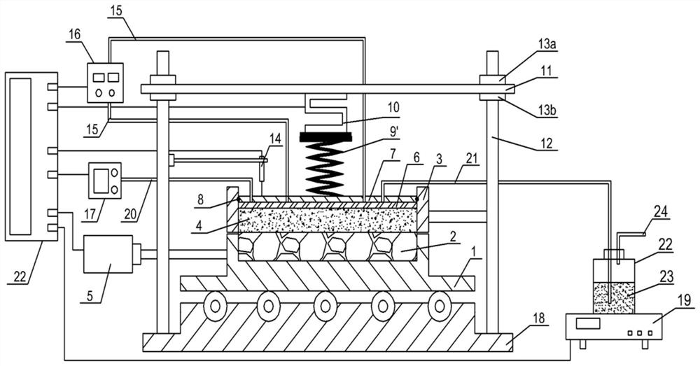
[0046] figure 1 Shown, a kind of embodiment of the present invention is, a kind of pile-soil interface shear strength test device that considers soil expansion and contraction behavior, comprises lower shear box 1, the pile body material 2 in lower shear box 1, The upper shear box 3 directly above the lower shear box 1, the soil sample 4 in the upper shear box 3 and the tangential shearing device 5 are characterized in that:
[0047] The lower shear box 1 is placed on the rollers of the bottom plate 18, and the two sides of the bottom plate 18 are fixed with uprights 12, and the top of the uprights 12 passes through the connecting through hole on the side of the cross bar 11, and is above the cross bar 11. The vertical rod 12 is connected with a fixed nut 13a, and the vertical rod 12 below the cross bar 11 is connected with a support nut 13b;
[0048] The soil sample 4 in the upper shear box 3 is covered with a metal permeable stone 6, and the metal permeable stone 6 is cover...
Embodiment 2
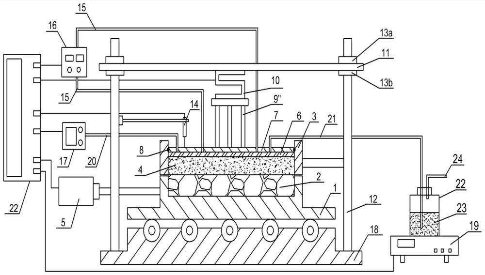
[0062] figure 2 It is shown that the structure of the pile-soil interface shear strength test device of this example is basically the same as that of Example 1, the only difference is that the force transmission member of this example is a rigid force transmission frame 9″ composed of more than one rigid rod.
[0063] Using the pile-soil interface shear strength test device considering the expansion and contraction behavior of the soil in this example, the method for carrying out the pile-soil interface shear strength test is as follows:
[0064] A, before the test, measure and record the initial moisture content, initial dry density and initial mass of the soil sample 4 in the upper shear box 3;
[0065] B. Loosen the support nut 13b on the vertical bar 12 downwards, then apply downward normal loads to the set test load value on the cross bar 11 step by step, and then adjust the fixing nut 13a to keep the cross bar 11 to maintain the test load value; then, carry out the ope...
Embodiment 3
[0072] figure 1 It shows that the structure of the pile-soil interface shear strength test device of this example is exactly the same as that of Example 1.
[0073] Using the pile-soil interface shear strength test device considering the expansion and contraction behavior of the soil in this example, the method for carrying out the pile-soil interface shear strength test is as follows:
[0074] A, before the test, measure and record the initial moisture content, initial dry density and initial mass of the soil sample 4 in the upper shear box 3;
[0075] B. Loosen the support nut 13b on the vertical bar 12 downwards, then apply downward normal loads to the set test load value on the cross bar 11 step by step, and then adjust the fixing nut 13a to keep the cross bar 11 to maintain the test load value; then, carry out the operation of step C
[0076] C, open the water outlet device 16, water enters the soil sample 4 through the water inlet pipe 15 and the metal permeable stone ...
PUM
 Abstract
Description
Claims
Application Information
 - R&D
- Intellectual Property
- Life Sciences
- Materials
- Tech Scout
- Unparalleled Data Quality
- Higher Quality Content
- 60% Fewer Hallucinations
Browse by: Latest US Patents, China's latest patents, Technical Efficacy Thesaurus, Application Domain, Technology Topic, Popular Technical Reports.
© 2025 PatSnap. All rights reserved.Legal|Privacy policy|Modern Slavery Act Transparency Statement|Sitemap|About US| Contact US: help@patsnap.com


