Laboratory organic waste liquid on-site real-time treatment system
An organic waste liquid, real-time treatment technology, applied in the direction of reducing greenhouse gases, combustion methods, lighting and heating equipment, etc., can solve the problems of untimely waste treatment, low waste treatment cost, leakage, etc. Efficiency, ensuring temperature and time, increasing the effect of the reaction process
- Summary
- Abstract
- Description
- Claims
- Application Information
AI Technical Summary
Problems solved by technology
Method used
Image
Examples
Embodiment 1
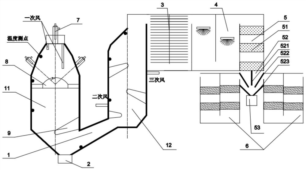
[0054] Embodiment 1 of the present invention provides an on-site real-time treatment system for laboratory organic waste liquid. The structure of the system is as follows: figure 1 shown, incl. Waste liquid reaction device 1, slag particle recovery tank 2, waste heat recovery device 3, flue gas quenching and desulfurization integrated device 4, dehydration device 5, flue gas purification device 6, waste liquid injection device 7, flame stabilizer 8 and diversion arch 9.
[0055] The waste liquid reaction device 1 includes a primary reaction body 11 and a secondary reaction body 12; a through hole is opened on the side of the primary reaction body 11 near the bottom, and communicates with the secondary reaction body 12 through an inclined upward connecting channel. The angle between the direction of the channel and the horizontal direction is 15°-45°; the bottom of the primary reaction body 11 is provided with a slag particle recovery tank 2; the interior of the primary reacti...
Embodiment 2
[0085] In embodiment two, the waste liquid reaction device 1 is as follows Figure 4 Shown structure, its difference with embodiment 1 has:
[0086] The waste liquid reaction device 1 includes a primary reaction body 11 and a secondary reaction body 12 ; the lower part of the primary reaction body 11 enters the upper part of the secondary reaction body 12 through a channel.
[0087] A divider 121 is arranged in the middle of the secondary reaction body 12 to divide the secondary reaction body 12 into a first reaction chamber and a second reaction chamber, and there is a gap between the flow divider and the bottom of the secondary reaction body 12, so that the The reactants produced by the reaction in the first reaction chamber enter the second reaction chamber through the gap. The upper part of the second reaction chamber is the end of the waste liquid reaction device 1, and the end is provided with a waste heat recovery device 3, a flue gas rapid cooling and desulfurization ...
Embodiment 3
[0089] In the third embodiment, the structure of the dehydration device 5 and the number and arrangement position of the flue gas purification device 6 are different from those in the above-mentioned embodiment. The combined structure of the dehydration device 5 and the flue gas purification device 6 is as follows Figure 5 shown.
[0090] Depend on Figure 5 It can be seen that the dehydration device 5 in the third embodiment still includes a pre-order dehydration device 51 , a terminal dehydration device 52 and a water collection tank 53 .
[0091] The pre-sequence dehydration device 51 is equipped with a multi-stage dehydration body (such as a secondary dehydration body). The dehydration body is made of polyurethane composite material. Enter the terminal dehydration device 52.
[0092] The walls of the terminal dehydration device 52 are all provided with dehydration material linings. The terminal dehydration device 52 includes a vertical baffle 521 , an inclined baffle 5...
PUM
 Abstract
Description
Claims
Application Information
 - R&D Engineer
- R&D Manager
- IP Professional
- Industry Leading Data Capabilities
- Powerful AI technology
- Patent DNA Extraction
Browse by: Latest US Patents, China's latest patents, Technical Efficacy Thesaurus, Application Domain, Technology Topic, Popular Technical Reports.
© 2024 PatSnap. All rights reserved.Legal|Privacy policy|Modern Slavery Act Transparency Statement|Sitemap|About US| Contact US: help@patsnap.com


